Here is the power circuit diagram of a mono Gree air conditioner using IC TNY277. The diagram creates two main power levels: 5V and 12V.
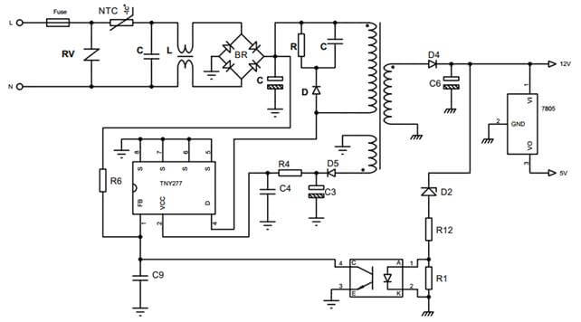
Operating principle:
After the 220V power source is rectified and filtered, it will produce a direct current (DC) voltage of 300V. This DC voltage will then pass through TN277, where it will be converted into a high frequency pulse series and sent through the pulse transformer. The voltage on the transformer’s secondary side will then be filtered and rectified by half to obtain the output voltage.
+ Voltage feedback circuit: D2, R12, R1, optocoupler.
+ 12V is regulated to 5V through voltage regulator IC 7805 for microprocessor.
What is TNY277?
TNY277 the IC family uses an ON/OFF control scheme and offers a design flexible solution with a low system cost and extended power capability. Peak output power: 23.5W.
Applications: Chargers/adapters for cell/cordless phones, PDAs, digital cameras, MP3/portable audio, shavers, etc.
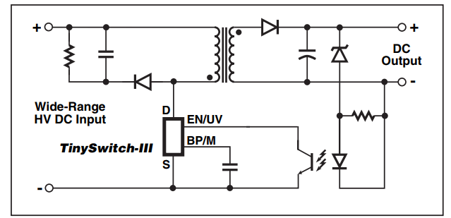
Typical Standby Application
1. FB (EN/EU): enable/under-voltage pin
This pin has two functions: output voltage feedback and senses line under-voltage conditions through an external resistor connected to the DC line voltage.
2. VCC (BP/M): bypass/multi-function pin
It is connected to a capacitor and diode to create power for the Mosfet trigger circuit inside the IC.
4. D: Drain pin
This pin is the power MOSFET drain connection. It provides internal operating current for both start-up and steady-state operation
5, 6, 7, 8. S: Source pin
This pin is internally connected to the output MOSFET source for high voltage power return and control circuit common
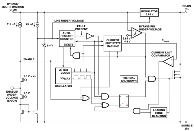
TNY277 Functional Block Diagram