Learn about different dc motor speed control circuit diagram that are widely used in various applications, each with its own set of advantages and disadvantages.
The principle of speed control of a DC motor
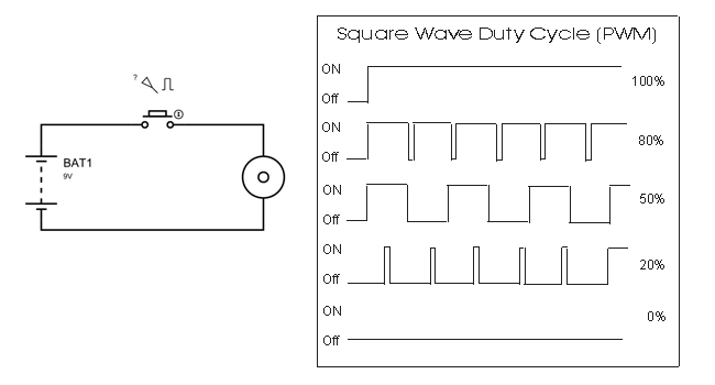
The speed of a DC motor changes when the voltage applied to it is changed. Voltage can be changed by applying a linear voltage or by using pulse width modulation.
One commonly used method for controlling a DC motor is the Pulse Width Modulation (PWM) method. In this method, the speed of the motor depends on the modulating voltage. The higher the voltage, the faster the electric motor rotates. PWM is an excellent technique for controlling analog circuits of motors with digital output from a microcontroller.
The speed of the motor can be controlled by altering the width of the control pulse. When the duty cycle is 0%, the motor will stop completely because there is no voltage difference. When the duty cycle is 50%, the motor will rotate at half the speed of the maximum speed because the voltage is half the full voltage. When PWM is in 100% condition, the motor rotates with maximum speed because of the continuous output of PWM.
Some dc motor speed control circuit diagram
1. Motor control using Mosfet
We present the simplest circuit that can regulate the speed of a DC motor by modifying the linear voltage applied to both ends of the motor.
When we adjust the variable resistor, it alters the voltage supplied to the G pin of mosfet Q1. As the voltage at pin G increases, the voltage drop across the mosfet decreases, resulting in a higher voltage supplied to both ends of the motor, thus causing an increase in the motor’s speed.
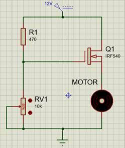
A basic circuit with only a few components can regulate the voltage of a small DC motor with low power capacity. This circuit has its limitations as the voltage drop across the Mosfet is high, limiting the capacity. If the motor is too large, the Mosfet will overheat and eventually fail.
2. DC motor speed control circuit diagram with IC 555
The 555 timer IC is a versatile integrated circuit used in timing, delay, pulse generation, and oscillator applications. It is popular due to its cost-effectiveness.
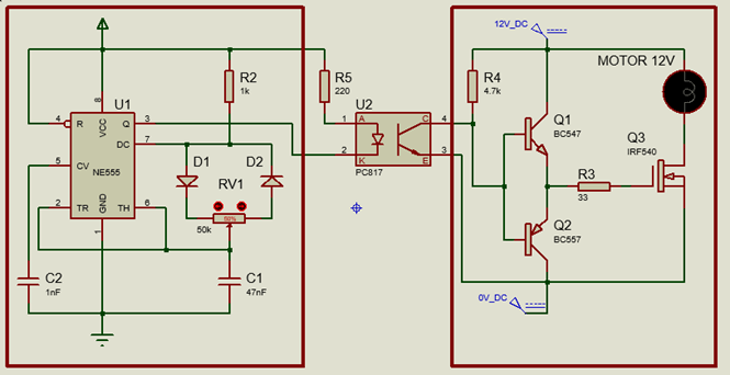
In applications where motor speed control is necessary, the IC555 is responsible for emitting control pulses with varying pulse widths and frequencies. To change the pulse width, the voltage set to pin 6 (TH) of the IC can be adjusted. The circuit below utilizes a variable resistor to control the width of the control pulse.
PC817 is an isolated optocoupler that helps prevent the power circuit from affecting the control circuit. The control pulse passes through the optocoupler and is then buffered by two transistors, Q1 and Q2, to match the high-frequency opening and closing speed of Mosfet Q3.
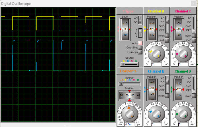
I will be using an oscilloscope to measure the waveform of the pulse from the IC, which is shown in yellow, and the voltage at the G terminal of Mosfet Q3, which is shown in blue. The amplitude of the pulse emitted from NE555 is 5V, while the pulse amplitude at terminal G is 12V. We know that the stimulation voltage required for the mosfet to conduct saturation is 10-20V, so the stimulation meets the necessary requirements.
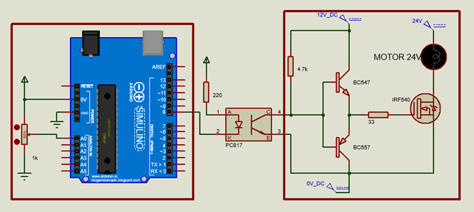
3. Control dc motor with arduino
Instead of using NE555 in this circuit, we are using an Arduino microchip which contains an AVR family microprocessor. Programming and loading code onto the Arduino board is simple and easy, even for those who don’t know how to program. All you need to do is install the IDE application, copy the program provided below, and download it onto the Arduino board.
To capture the voltage changes made by the user in the potentiometer, we use pin A0. The Arduino then produces a control pulse with pulse width proportional to the value recorded at pin A0. The driving circuit and power circuit function similarly to the circuit that uses IC555.
Readers can download the code for Arduino here.
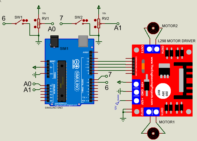
4. Control dc motor speed with H-bridge circuit
Module L298N is a commonly used H-bridge module that can be easily purchased online. It can control one stepper motor or two DC motors simultaneously.
The circuit below utilizes the H-bridge circuit module to manage the direction and speed of two DC motors. The Arduino uses pins 6 and 7 to monitor the status of two switches, SW1 and SW2, to control the direction of rotation. Additionally, the Arduino uses pins A0 and A1 to read the values of two potentiometers, which in turn control the speed of the motors.
Code for Arduino to control two DC motors can be downloaded here.
The H-bridge module is affordable and user-friendly, but its capacity is limited to 25W and can control a motor with a maximum current of 2A.
>>> Related articles:
12v dc motor forward and reverse circuit
What is carrier frequency In VFD
L298n motor driver connection with arduino – Code, Circuit Diagram, Video
>>> Video simulating the operation of the L298 module