What is a flyback converter circuit? Explore the general diagram and principle of a basic flyback circuit.
What is flyback converter circuit?
The flyback converter, also known as an isolated buck-boost converter, is a simple circuit used to regulate a system’s output voltage. It can produce an output voltage that is either greater than or less than the input voltage, depending on the duty cycle of the switching pulse.
The input and output voltages are isolated through the use of a pulse transformer. Flyback circuits are commonly employed in chargers that require low power, such as medical devices, televisions, laptops, and phones.
The advantage of the flyback circuit is that the circuit is smaller in size than a rectifier circuit using a linear transformer of the same capacity. However, the flyback circuit principle is more complicated.
Structure and principle
1. Structure
Mosfet Q1: Switching with high frequency (For example: 50 kHz).
Rshunt, R2: Current feedback resistor to the control circuit.
Pulse transformer: Converts voltage to another level at the same frequency.
D1, R1, C1: Reverse pulse suppression circuit from the transformer to protect the mosfet Q1.
D2, C2: Rectify and filter the secondary voltage.
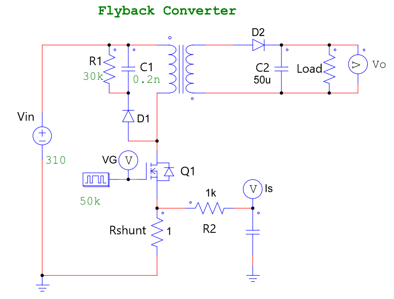
Flyback converter circuit
2. Flyback converter circuit working principle
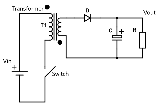
When the voltage signal at pin G is high, the Mosfet acts like a switch in the closed state. The primary coil of the transformer is directly connected to the input voltage source (Vin).
When the voltage pin signal G is low, the MOSFET does not conduct electricity like a switch in the open state. The transformer primary coil is not energized.
The primary coil of the transformer is energized and de-energized in a sequence that creates a fluctuating magnetic field in the ferrite core. This magnetic field generates a voltage in the secondary coil. Subsequently, this voltage is rectified and filtered across D2 and C2.
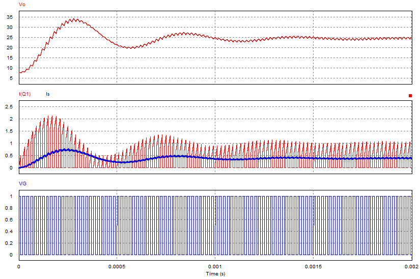
Note: The image below depicts a simulated waveform with a frequency of 50 kHz over a period from 0 to 0.002s.
In fact, flyback converter circuits also have a voltage feedback circuit to maintain stable output voltage as the load changes. Some application circuits utilizing flyback circuits will be presented in the upcoming articles.
>>> Related articles:
Flyback circuit using TNY277 (gree airconditioner)
4047 Inverter Circuit Diagram – How it work?
Single phase half wave uncontrolled rectifier (5 circuits)