What is a Single phase half wave uncontrolled rectifier? Working principle of five half-wave rectifier circuit diagrams with R, RL, RLE load. Let’s find out in the article below.
What is a half wave uncontrolled rectifier?
A single phase half-wave uncontrolled rectifier is a circuit that converts AC voltage to DC voltage in half a cycle of the mains voltage. In a half-cycle rectifier circuit, the power source will be connected in series with the load through Diode.
Working of half-wave uncontrolled rectifier: in the positive half-cycle, the diode is forward biased. The diode works as a closed switch, allowing current to flow through the load. In the negative half-cycle, the diode is reverse biased. The diode works as an open switch, so no current flows in the circuit.
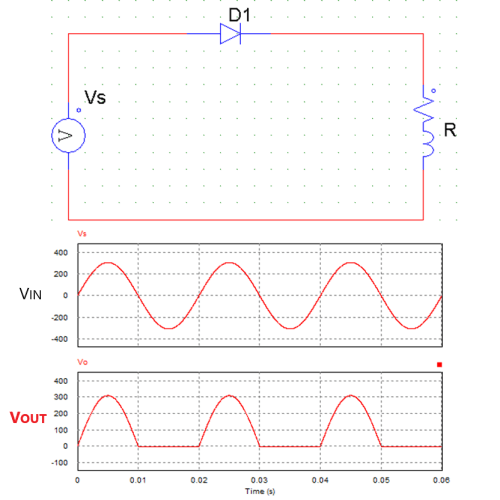
Single phase half wave uncontrolled rectifier with r load
A half-wave rectifier is the most basic of the rectifier circuits. The advantage of this circuit is that it is easy and inexpensive. The disadvantage of this circuit is low voltage quality, and the average voltage will be smaller.
For applications that require small output voltage and power, a transformer can be used to reduce the AC supply voltage. The circuit diagram using a transformer shown below. The voltage in the secondary coil decreases with the ratio of the transformer.
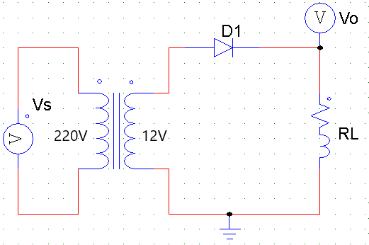
The rectifier circuit with transformer
Single phase half wave uncontrolled rectifier (5 circuits)
The examples below use AC supply voltage, VRMS = 220V and frequency is f = 50Hz: Vs = 220√2Sin(100πt)
1. Half wave rectifier with r load
Single phase half wave uncontrolled rectifier with R load and output waveform shown below. The output load is a resistor R = 10 Ohm connected with the power source through diode D1.
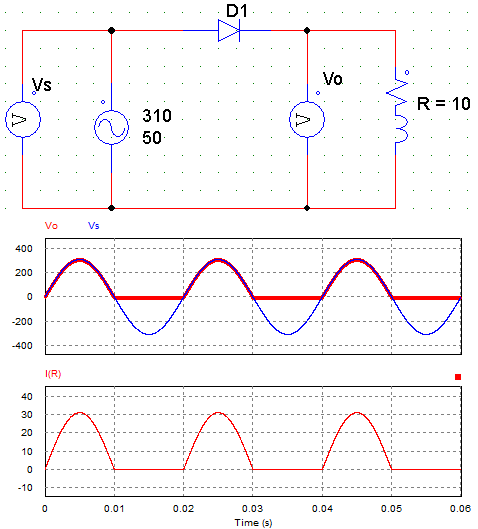
Half-wave rectifier circuit with R load
– Working principle:
+ In the positive half cycle Vs > 0: the diode will be forward biased. Diode conducts as a closed switch. Therefore the voltage across the load R equals the supply voltage Vs: Vo = Vs. The output waveform of the current, in this case, is the same as the voltage waveform.
+ In the negative half cycle Vs <0: the diode will be reverse biased. Diode don’t allow the current through it. So no current flows in this circuit. The output voltage Vo = 0V.
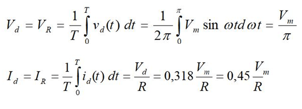
– Output average voltage (Ud) and output average current (Id) with R load:
2. Single phase half wave uncontrolled rectifier with rl load
Circuit diagram of half wave rectifier with RL load is as follows:
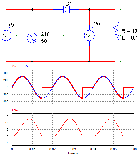
Single phase half-wave uncontrolled rectifier circuit with RL load
– Working principle:
+ In the positive half cycle: Similar with the rectifier circuit with R load, the diode will turn ON, so Vo = Vs.
+ In the negative cycle: When the voltage on the RL load is zero, the RL load becomes a power source that generates a current in the same direction as the previous current. Diode continues to conduct so Vo = Vs <0, Io > 0. Until RL load runs out of energy so diode stops conduct; the output voltage is zero (Vo = 0, Io = 0).
The current generation time depends on the large or small value of the inductor. At this time, the output voltage is less than zero: Vo = Vs < 0.
=> With RL load, the output voltage has a negative part, so it reduces the quality of the output voltage. To overcome this drawback, people use an additional flyback diode.
3. Half wave rectifier with flyback diode
The rectifier circuit uses an additional flyback diode to eliminate negative currents when the load is inductive. People will parallel RL load with a diode Df shown in the figure below.
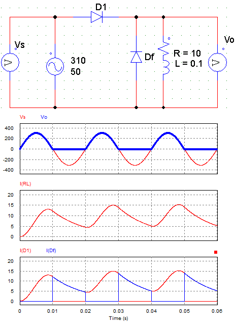
Single phse half-wave rectifier with flyback diode
– Working principle:
+ In the positive half-cycle: Diode D1 conduct so Vo = Vs > 0. The current lags the phase compared to the voltage. When the voltage is zero, the current is still positive.
+ In the negative half-cycle: Diode D1 turns off due to reverse bias, the load generates energy through Diode Df. So the two load terminals are shorted => Vo = 0.
The current through the diode Df is the current through the load in the negative cycle. If the value of L is large enough, the load current will always be greater than 0 (continuous load current). If L is small, the load current is interrupted.
4. Half wave rectifier circuit with RLE load
+ RLE load can be a DC motor (R + L + E).
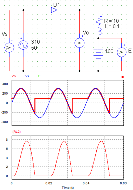
Half wave rectifier circuit with RLE Load
– The working principle:
+ In the positive half cycle:
* When Vs < E: the diode is reverse biased, diode does not conduct. The outphut voltage is equal to E: Vo = E = 100V
* When Vs > E: the diode conduct so Vo = Vs.
* At the end of the positive half-cycle, when Vs < E: the diode is reverse biased. But the Load generates current in the same direction as the previous current, so the diode continues to conduct. The output voltage Vo continues to be equal to Vs (Vo = Vs).
+ In the negative half cycle: Diode continues in conduction state, so Vo = Vs < 0. Until the load current runs out of energy. Then the diode stops conducting (Vo = E = 100V).
5. Rectifier circuit using capacitor
The output waveform of the half-wave rectifier has a large ripple. We often use capacitors to filter and smooth the output voltage. Capacitance values of capacitors are very complicated to calculate, so people often use software to simulate and choose suitable capacitor values.
The advantage of a half-wave rectifier using a capacitor is that when the output voltage reaches a steady-state, the voltage will stabilize in the form of a straight line. The average value of the voltage is equal to the amplitude value of the source voltage.
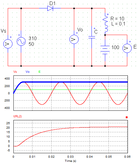
Rectifier circuit using capacitor
The working principle of single-phase half wave uncontrolled rectifier using a filter capacitor is simple. Because the capacitor is connected in parallel with the load, the output voltage is equal to the voltage of the capacitor (Vo = Vc). In the first cycle, when the voltage increases, the capacitor is charged until voltage of capacitor is equal to the peak voltage of the source (Vc = Vmax).
If the value of the capacitor is small, then when the voltage of the capacitor is less than the source voltage (Vc < Vs), the diode will conduct. And the capacitor continues to be charged.
FAQ about Single phase half-cycle uncontrolled rectifier
+ Why it is called half-wave rectifier?
Because the diode only conducts in one direction, the current is rectified only during the positive half-cycle of the power supply. In the negative cycle, there is no current in the circuit. Hence, it is called a half-wave rectifier.
+ What is the difference between half wave rectifier and full wave rectifier?
Single phase half-wave uncontrolled rectifiers use only one diode, while full-wave rectifiers use two or four diodes.
The input AC voltage in the full-wave rectifier circuit is rectified to DC voltage in both cycles. The average output voltage and the power is larger than the half-wave rectifier circuit.
+ Why capacitor is used in the rectifier circuit?
The output voltage in the rectifier circuit is DC voltage, but it is not a pure DC. To smooth the voltage and eliminate these ripples, a capacitor is connected in parallel with the load.
In addition, when using filter capacitors, the average output voltage also increases, the power source is more stable.
>>> See also: Working principle of the half-wave rectifier circuit
>> Related posts:
Working of single phase bridge rectifier (10 circuits)
Single phase full wave rectifier (6 circuits)
8 schematic diagrams of 3 phase rectifier circuit