Installation instructions for basic parameters, wiring diagram, some examples of how to control GD200A inverter. Invt GD200A user manual pdf download
INVT GD200A inverter specifications
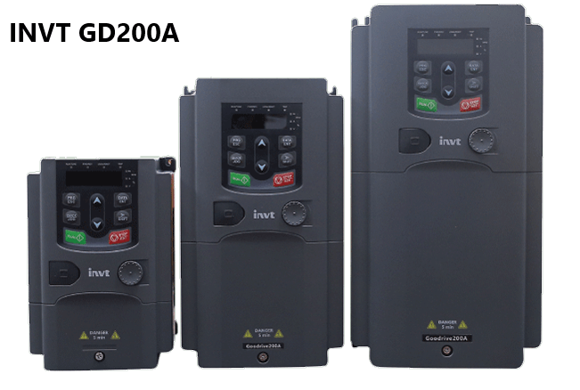
The new generation general-purpose inverter GD200A is used to control asynchronous motors. Goodrive200A is a versatile inverter series, controlled by a high-speed 32-bit DSP processor from Texas Instruments. Allows the implementation of modern, optimized control algorithms, providing outstanding performance.
Goodrive200A has a wide power range and a wide range of control features for most industrial applications. Goodrive200A is used for variable torque loads as pump, exhaust fan; and constant torque loads as conveyors, mixers, and rolling mills.
About GD200A inverter
– Power range of inverter GD200A
+ 3 phase 220V: 0.75 kW to 55 kW
+ 3 phase 380V: from 0.75 kW to 500 kW
– Analog Input:
+ 2 channels AI1 and AI2 with signal 0 – 10V/0 – 20mA
+ 1 channel AI3 with signal – 10 to 10V
– Analog output: 2 channels AO1, AO2 with signal 0 – 10V/0 – 20mA
– Digital input:
+ 8 digital input channels with multiple selectable functions
+ 1 channel high speed input (max 50khz)
– Digital output
+ 1 high-speed output channel
+ 1 output channel (Y) in open collector form.
– Relay output: 2 channels
Parameter setting and wiring (GD200A Manual)
1. Wring
The general GD200A inverter wiring diagram is drawn as shown below:
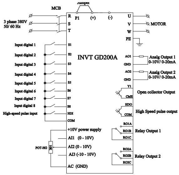
Wiring diagram of inverter GD200A
Basic wiring diagram:
+ Power pins R, S, T connect to 3-phase power supply.
+ Output pins U, V, W connected to 3 wires of the motor
+ Digital input pins S1, S2, S3… connected to the switch to control running, stopping…
+ Analog input pins AI1, AI2, AI3 can be connected to potentiometer for frequency control
+ Analog output pins with AO1, AO2 can be connected to measuring equipment to display frequency, current, and voltage.
2. Parameter setting
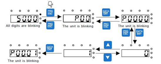
The installation procedure is carried out according to the following flowchart. The example below is changing the parameter P00.01 = 1 to P00.01 = 0 (the run command is executed on the keypad).
Download INVT GD200A Manual .pdf
Basic function group
|
Parameter |
Default value |
Explanation |
|
P00.01 |
0 |
Select the channel to execute the run command 0: Keypad 1: External Terminal 2: Communication |
|
P00.03 |
50.00Hz |
Max output frequency |
|
P00.04 |
50.00Hz |
Upper limit frequency |
|
P00.05 |
0Hz |
Lower limit frequency |
|
P00.11 |
… |
Acceleration time |
|
P00.12 |
… |
Deceleration time |
|
P00.18 |
0 |
Reset parameters to default values 0: Do not use this function 1: Restore default value 2: Clear error history 3: Lock all function codes |
Basic function group table
Three example of how to control GD200A Inverter
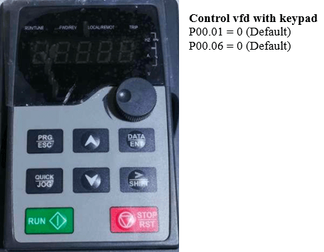
1. Control vfd with keypad
To control the inverter by keypad, the following parameters need to be set:
P00.01 = 0 control run, stop vfd by two buttons RUN, STOP.
P00.06 = 0 change the reference frequency by two buttons UP, DOWN; or set P00.06 = 1 to select frequency change by potentionmeter on keypad (AI1 analog input).
2. Control vfd with 3 position switch
– Parameter setting
+ P00.01 = 1 selects the control command to run and stop by an external switch.
+ P00.06 = 2 change the speed set by an external potentiometer connected to terminal AI2. (Default P00.07 = 2, so to change P00.06 = 2, we have to change parameter P00.07 with a number other than two first).
+ P05.01 = 1 select terminal S1 with forward running function.
+ P05.02 = 2 select terminal S2 with reverse running function.
– Wiring diagram
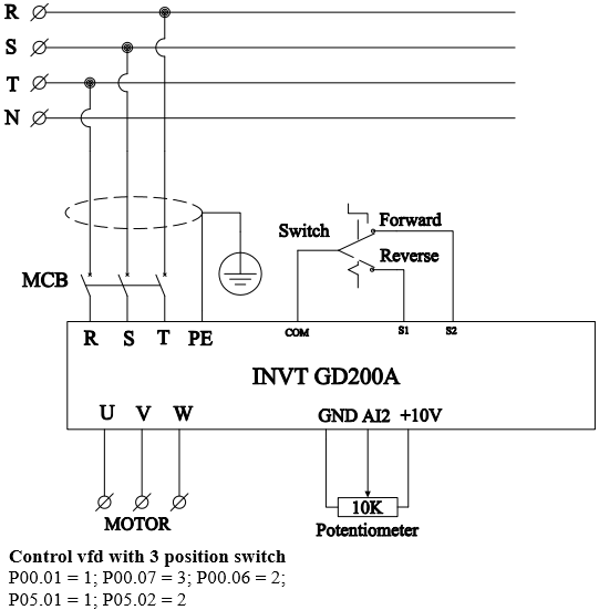
Setting up the inverter invt gd200a by external switch
3. Control vfd with push button
Instead of using switches, we can set the inverter to use push buttons.
– Parameter setting
+ P00.01 = 1 select the control command to run and stop by the push button.
+ P00.07 = 3 and P00.06 = 2 adjust the reference frequency by a potentiometer connected to terminal AI2.
+ P05.01 = 1 terminal S1 used to run forward.
+ P05.02 = 2 terminals S2 used to run reverse.
+ P05.03 = 3 terminals S3 used to stop (when S3 is closed, it is allowed to run. When S3 is open, the inverter executes the stop command)
+ P05.13 = 3 three-wire control mode settings
– Wiring diagram for vfd control with push button
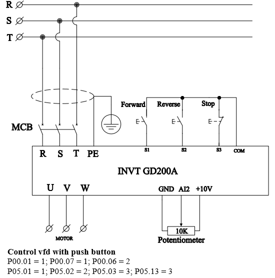
Control inverter invt gd200a by external push button, potentiometer.
>>> See also:
Chf100A
GD20
GD10
Down load INVT GD200A Manual. Here
Refer video: INVT GD20 “Setup Tutorial”