How to reverse a 3 phase motor (6 circuit diagrams), learning about the wiring diagram, the working principle, the advantages and disadvantages of each circuit.
Principle of reversing AC motor
The three-phase induction motor works on the principle that the force generated by the magnetic field affects the current flowing inside the rotor. The magnetic field in a three-phase motor is a rotating magnetic field, so when the motor is connected to the power supply, the rotor rotates with the magnetic field.
To reverse a 3-phase motor, we must change the direction of the rotating magnetic field. To do this, one would change two of the three wires of the motor when connected to power.
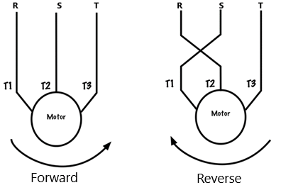
3 phase motors change direction when we change 2 of the 3 wires of the motor (pictured above). Because when we change the wiring of the motor as shown above, it will change the direction of the magnetic force acting on the rotor.
How to reverse a 3 phase motor (5 circuits)
1. Reversing circuit using switch
– Wiring diagram
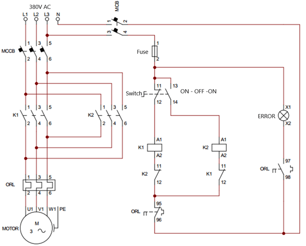
The reversing circuit of a 3-phase motor uses a 3-position switch to control 2 contactors (the figure below uses the 2-position switch symbol instead of the 3-position switch). One contactor is connected to the motor to run forward, the other when closed will swap two of the three wires of the motor.
How to reverse a 3 phase motor using switch
The 3-position switch (ON – OFF – ON) is two 2-position switches combined. The top two contacts of the two switches are connected together.
The contact on the bottom of the switch, one side connected to the contactor coil K1 to run forward. The other side is connected to the contactor coil K2 to run in reverse.
When turning the switch to the left or right, the circuit will supply power to the coil of contactor K1 or contactor K2.
The coil K1 connects to normally closed K2 (11 12), coil K2 connects normally closed K1 (11 12). To prevent two contactors K1 and K2 to close at the same time.
We connect the contactor coils in series with the normally closed of the thermal relay (ORL 95 96). When the motor is overloaded, the thermal relay will become active, causing the thermal relay contacts to change state. The normally closed contact of the ORL (95 96) opens and the normally open contact of the ORL (97 98) closes. At this point the motor is disconnected from the power supply and the ERROR light turns on.
– Advantages and disadvantages:
+ Advantages: Circuit is simple, easy to understand, overload protection, short circuit protection
+ Disadvantages: When power is lost, the motor will stop, if the switch is not turned to the OFF position, after power is restored, the motor will automatically run. This can be dangerous to the load and people.
2. Reversing circuit using push button
In industrial electrical cabinets, people will use two buttons ON and OFF instead of using switches.
– Wiring diagram
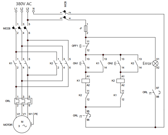
The figure below uses one OFF button and two ON buttons to control the motor forward and reverse. Because the push button contacts will return to the original position after we stop pressing. Therefore, to keep the contactor closed, we connect the ON1 button in parallel with the normally open contact of K1 (13 14). And connect ON2 in parallel with normally open contact K2 (13 14), after the ON button returns to the open state, current will pass through these contacts.
Reverse wiring diagram of 3-phase motor using push button
– Working principle of the circuit:
+ When the ON1 button is pressed, the contactor coil K1 is energized. Then the main contact of K1 closes, so the motor rotates in the forward direction. At the same time, the normally open contact of K1 (13 14) closes to keep the circuit closed.
+ At this time, the normally closed of K1 (11 12) will open. If we press the ON2 button, the circuit is still open, so coil K2 will not be energized. To reverse the motor, first we need to press the OFF button to stop the motor.
+ When contactor K1 is open, if ON2 is pressed, the main contact of K2 will be closed and the motor will run in the opposite direction.
+ Assuming the motor is overloaded, the thermal relay will be active, the thermal relay contacts will change state. These contacts disconnect the contactor coil from the power supply. As the motor stops rotating, the motor is protected from overheating.
– Advantages and disadvantages
+ Advantages: the circuit is stable, reliable, and safe for the operator. And the motor does not restart automatically after power is restored.
+ The disadvantage of this circuit is that the wiring is a bit more complicated than the circuit using a switch.
Refer to the simulation video about the AC motor reversing circuit
3. Using inverter to reverse the motor
The inverter is a specialized device for speed control, soft start, and reversing of 3-phase asynchronous motors. We can use the inverter to control the motor reverse. Here we take the inverter of INVT as an example to learn how to use the inverter to reverse a 3 phase motor.
– Wiring diagram
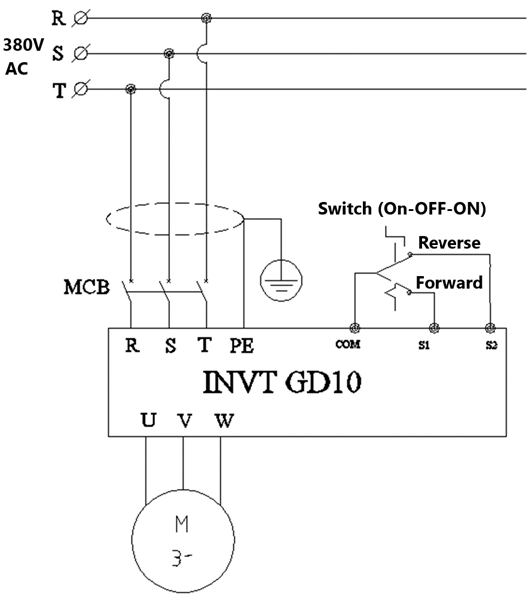
Wiring the motor to control rotation through the inverter is quite simple. Circuit diagram as shown below.
+ 3 phase voltage is connected to the R, S, T pins of the inverter; U, V, W inverter outputs are directly connected to the motor.
+ We use a 3-position switch to control the motor running forward and reverse. The bottom contact of the switch will connect to pins S1 and S2 of the inverter. The top contact of the switch is connected to the COM pin of the inverter.
The inverter can enable or disable the auto-run function after power failure. So it’s still safe to use the switch.
Wiring diagram for reversing motor using inverter
– Inverter parameter setting
*** Basic parameters
+ P00.18 = 1 returns factory default parameters
+ P00.03 = 50, P00.04 = 50 set the maximum frequency for the motor (default)
+ P00.11 = 5s acceleration time is 5 seconds (default)
+ P00.12 = 5s deceleration time is 5 seconds (default)
+ P01.21 = 0 disables auto-restart function after power failure (default)
*** Setting the mode Use an external switch to control the inverter
+ P00.01 = 1 select inverter control mode by external terminal
+ P05.01 = 1 Use pin S1 as forward function (default)
+ P00.02 = 2 Use pin S2 as reverse function
– Advantages and disadvantages
+ Advantages: The inverter is not only used to reverse the motor direction, but also control the speed, acceleration and deceleration time. In addition, the inverter also provides many motor protection functions such as overvoltage, undervoltage, overcurrent, phase loss, etc.
The disadvantage of the inverter method is that the cost of the inverter is quite high. The user must know how to set the basic parameters of the inverter.
4. Star Delta Forward and Reverse Starter
A very common method used to reduce the starting current for 3-phase motors and control the direction of the motor is Star Delta Forward and Reverse Starter.
The figure below is the circuit diagram of star-delta starter and motor reversing control using 4 contactors.
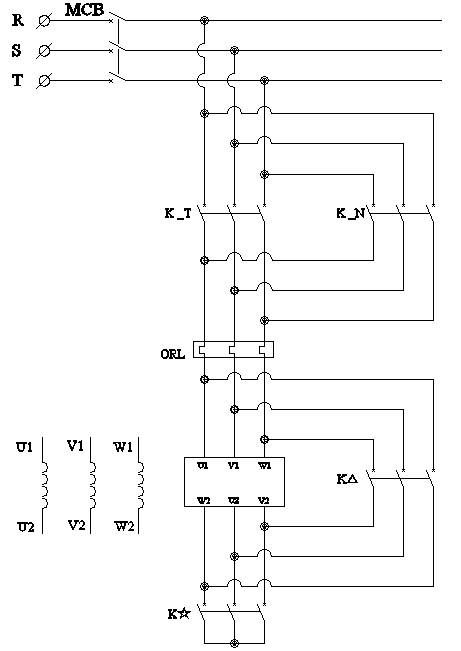
Power circuit: star delta forward and reverse starter
– Working principle
When the forward button is pressed, the contact of contactor K_T closes. Then the motor will start star delta mode in the forward direction.
When the motor is stopped. Press the reverse run button, the reverse contactor closes, the motor starts star delta mode but in the opposite direction.
For details on the diagram, the principle of the star delta forward and reverse starter circuit, please see the article below.
>>> See more: Learnings about the operating principle of 4 star-delta starter circuits (updating)
– Advantages and disadvantages
+ Advantages: The circuit can reverse the rotation of the motor and reduce the starting current by 3 times. If the application does not require speed control, the delta star starter circuit is used because of its low cost.
+ The disadvantage is that the circuit diagram and operating principle are quite complicated.
5. Using Programmable Logic Controller
The last method that we want to introduce to everyone. Reversing circuit of 3-phase motor using PLC. Usually people will not use PLC for reverse starting only, but people often use control of many applications at the same time.
– Wiring diagram
+ We will control the PLC through push buttons, connect the push buttons to the input of the PLC. Stop push button connected to pin X0, forward button connected to pin X1 and reverse button connected to pin X2.
+ Connect the relay outputs of the PLC to control the contactors. Coil contactor KM1 used to run forward will be connected to pin Y0, contactor KM2 used to run in reverse will connect to pin Y1.
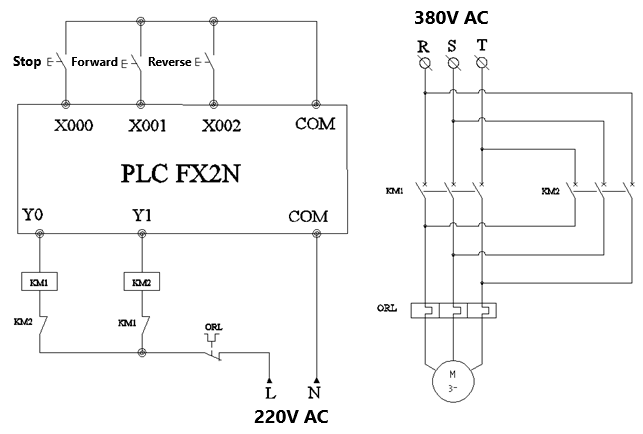
How to reverse a 3 phase motor using PLC
– Working principle
The PLC scans the inputs to read the button’s state, then processes the program written by the user and changes the output state. The reverse control program is written as shown below.
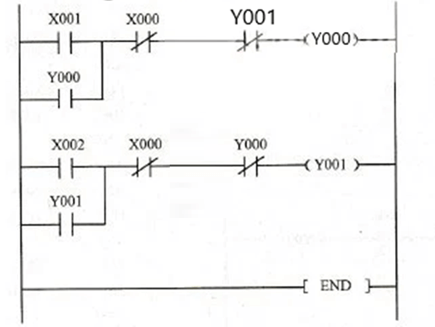
Motor reversing program with PLC Mitsubishi
+ Assume that, when we press the forward button, pin X1 is ON, output Y0 turns on. Normally open contact Y0 is connected in parallel with X1 to maintain itself after the push button returns to the open state.
+ When Y0 is turned on, the Y0 and COM pins are connected, so the contactor coil KM1 is energized. The motor will rotate in the forward direction.
+ Similarly for the reverse direction, when the reverse button is pressed, the PLC activates pin Y1. Therefore, the main contact of contactor KM2 closes, the motor rotates in the opposite direction.
>>> See more:
What is contactor? Best article about contactor
4 circuit diagram of star-delta starter
single phase contactor wiring diagram (4 circuit diagrams)