Learn about full wave center tapped rectifier with capacitor filter. Principle of full wave rectifier circuit using two diodes and explain why filter capacitors are used.
Full wave rectification using two diodes
– Working principle
The source voltage with frequency is f = 50Hz => The period of the voltage is T = 0.02 seconds.
+ In the range 0 < t < 0.01: voltage V1 > 0 and V2 < 0, so D2 conducts and D1 is reverse biased. Then D2 is subjected to twice the secondary voltage of the transformer (reverse voltage of D2). The voltage is rectified through Diode D1 and the output voltage is equal to the source voltage.
+ In the range 0.01 < t < 0.02: V1 < 0 and V2 > 0, so D2 conducts and D1 is reverse biased. The voltage is rectified through Diode D2 and the output voltage is opposite to the source voltage (Vout = -Vin).
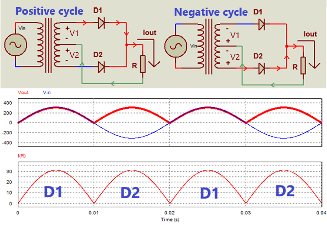
Working principle of full wave rectifier circuit
– Output voltage and current formula
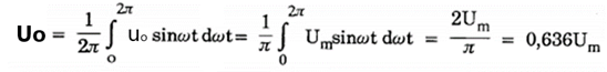
Assume that, the equation for the supply voltage is: V1 = -V2 = Um.sin(wt)
+ Average value of output voltage:
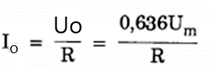
+ Average value of load current:
+ Each diode conducts in half cycle, so the average current through each diode is:

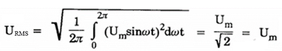
+ Root Mean Square Voltage
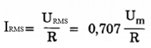
+ Root mean square current
Full wave center tapped rectifier with capacitor filter
– Why use filter capacitors?
As we all know, the output waveform of a full-wave rectifier is not a standard DC voltage. To reduce the ripple and increase the average output voltage, a filter capacitor will be used in parallel with the output.
Full wave center tapped rectifier with capacitor filter diagram as shown below.
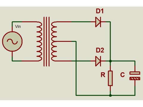
Full-wave rectifier circuit using two diodes with filter capacitor
– Working principle
In the first positive half-cycle, when the supply voltage increases, Diode D1 is forward biased. Then the capacitor is charged through D1. The capacitor is parallel to the load, so the voltage across the capacitor is the output voltage of the rectifier circuit. When the capacitor value is large, the charging current for the capacitor is also large, so we can see the current through diode D1 increase dramatically.
When the voltage value on the capacitor is higher than the value of the source voltage, D1 is reversed. The capacitor starts to discharge through the load, the larger the capacitor value, the smaller the voltage drop rate. When the voltage across the capacitor is lower than the source voltage, the capacitor will charge again.
If the capacitor value is large enough, then after the circuit stabilizes, the output current and voltage waveform will be a straight line.
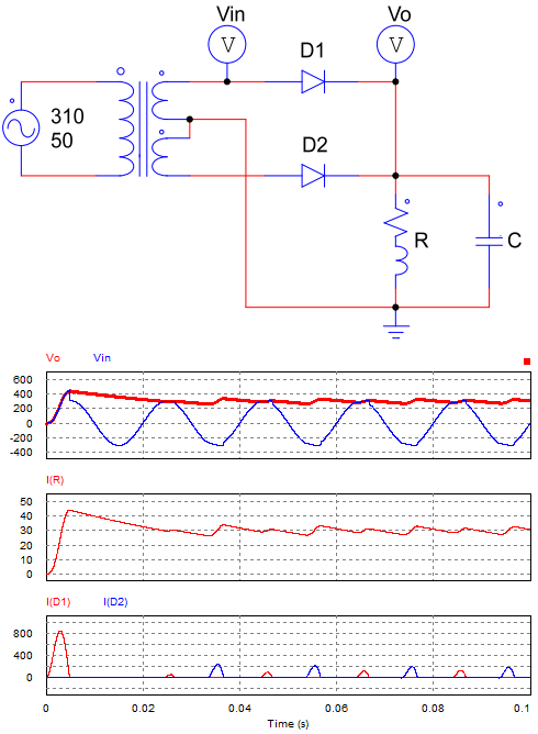
Output waveform of the circuit using filter capacitor
Conclusion: The circuit using filter capacitor has smaller ripple, better quality of output voltage and current. The calculation and selection of the capacitor value is very complicated. We can use simulation on the software to choose the appropriate capacitor value.
Refer to video simulation circuit using filter capacitor with load R = 50 Ohm, Capacitor values are: 0.1, 470, 2000 uF.