What is contactor? The most detailed article on structure, operating principle, function, calculation and selection of contactor. Answers to some frequently asked questions about contactor.
1. What is contactor, why are contactor used
1.1 What is contactor
Contactor is an electromechanical switch, used to connect and disconnect the power source with the load. The contactor is voltage controlled, the current to drive the contactor is much lower than the current flowing through the load. The contactor combine with a thermal relay is called a magnetic starter.
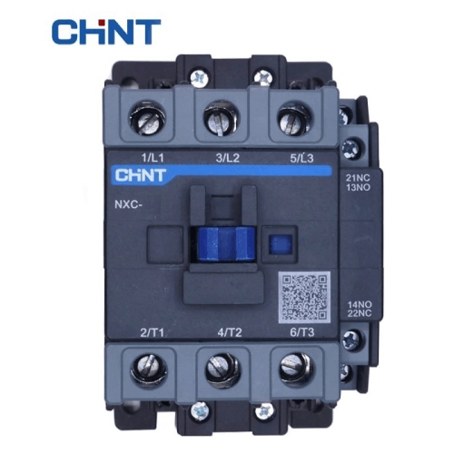
What is contactor?
Magnetic starter applications include: electric motor control, lighting equipment, heating systems and other equipment.
Contactors come in a variety of sizes and capacities. From a few amps to several tens of thousands of amps, voltages up to several kV. In large capacity contactors are equipped with an arc extinguishing system to protect its contacts.
1.2 Why do we use Magnetic starter
The Magnetic starter uses low voltage to control the motor switch with high voltage, high current. So the magnetic starter is used as a power amplifier.
Assume that, we need to use PLC to control three phase motor. The output of the PLC can only control the load from 24V to 220V with small current. Connecting the contactor directly to the load with high voltage and current will lead to output damage. In this case, we will use the PLC to control the contactor to switch the motor.
For example, we use a contactor with a control voltage of 24V. In the normal state the contact of the contactor is open. When the PLC outputs 24V DC to the contactor coil, the contacts will close, connecting the three-phase power to the motor.
Thus, the PLC will switch the motor indirectly, so the PLC output will be isolated from high voltage and load current. The figure below shows the principle of this example.
Why do we use Magnetic starter – RealPars
2. Structure and working principle of contactor
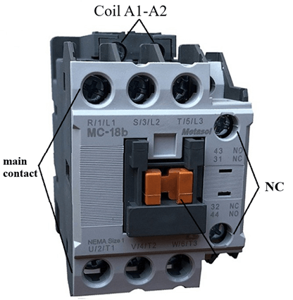
2.1 Structure of the contactor
The structure of the contactor consists of 3 main components: the electromagnetic mechanism and the system of contacts and protective cover.
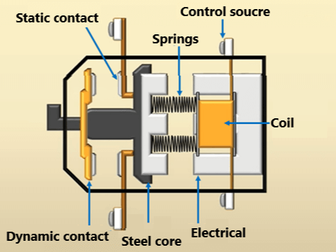
Construction of a Contactor
a. The electromagnetic mechanism
Consists of a coil wrapped around an electromagnetic core, when powered, it will act as an electromagnet to create an attractive force to close the contact.
The coil can be controlled by either DC or AC voltage. This voltage comes from an external control circuit. For contactor with coil rated voltage of AC, the ferromagnetic core is made of many steel sheets to reduce losses due to eddy currents. For DC contactor, the core is made of solid steel.
+ This electromagnetic core consists of a dynamic part and a static part, these two parts are connected by springs. The moving part is connected to the movable contact rod. When the magnetic force generated by the coil is greater than the spring force, the two contacts will connect. Conversely, when the magnetic force is less than the spring force, the two contacts will be disconnected.
b. Contact system
There are two types of contacts, main contacts and auxiliary contacts.
+ The main contact has the function of carrying the load current, the current value is large. The main contact in the normal state is the open state. When the contactor is energized, the contact changes to the closed state.
+ Auxiliary contact: Depending on the type of contactor, there are 1, 2 or no auxiliary contacts. Auxiliary contacts are of two types, normally open and normally closed.
* Normally Closed Contact (NC): A contact that in the normal state will be in the closed state. When the contactor coil is energized, it will switch to the open state. When the coil loses power, the contact will return to the normally closed state.
* Normally open contact (NO): is a contact which in the normal state is the open state. When power is applied to the contactor, the contact switches to the closed state.
c. Plastic cover
To protect the contactor’s internal elements from dust, weather and as a protective insulating layer for the user.
*** In addition, in some types of large capacity contactor, there is an additional arc extinguishing system. Because when the contactor switches a large amount of electrical power, an arc with a large current will be generated on the contact. Therefore, arc extinguishing is required to ensure long-term operation of the contacts.
2.2 Working principle
The working principle of the contactor is presented as follows:
When the coil of the contactor is energized, the coil immediately becomes an electromagnet, generating an electromagnetic force greater than the spring force. This force pulls the movable contact toward the static contact to form a closed circuit that allows current to flow. Thanks to the bonding elements, the auxiliary contacts also change their state from closed to open and vice versa.
+ When the coil is not energized, the spring expands to push the movable contact part back to its original position. The main contactor of the contactor returns to the open state, and the auxiliary contacts also return to the original state.
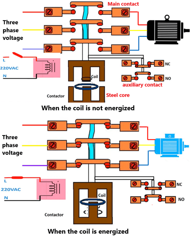
What is the working principle of contactor? – Electricalonline4u
Video about working principle magnetic starter – Realpars
3. Classification and designation
– Classification of contactors:
+ By voltage type: DC and AC contactors
+ According to coil voltage: AC voltage: 220V, 380V. DC voltage: 24V, 48V.
+ Classified by working current: 9A, 12A, 18A…
+ Classification according to the principle of transmission: magnetic contactor, hydraulic type…
+ According to the number of poles of the main contact: 1P, 2P, 3P, 4P. In industry 3 pole contactors are most commonly used.
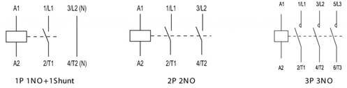
Classify contactors by number of poles
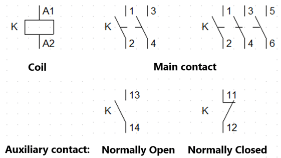
– Symbols of contactors in electrical drawings
4. The characteristic of magnetic starter
– Rated voltage
Rated voltage (U) is the voltage applied to the coil of the contactor. The coil will work normally with voltage levels in the range of 85 – 105% U.
+ A voltage lower than the rated voltage will result in the electromagnetic force being less than the spring force. Thus the state of the contact does not change or may close tightly.
+ Voltage higher than rated voltage may burn the coil.
– Rated working current
The rated current I is the current that is allowed to pass through the main contact. People measured at the rated current value, contactor should not operate continuously for no more than 8 hours.
If the magnetic starter is placed in a poorly cooled environment, the current capacity will be reduced. Therefore, it is necessary to apply cooling measures to ensure capacity. Or can choose the magnetic starter operating current greater than 10% to ensure stable operation.
– Switching capacity
When the motor is started, the motor starting current is times larger than the rated current of the motor. So the contactor must be able to close 5-7 times Idm.
The magnetic starter can switch loads up to 10 times the rated current with inductive loads.
– Switching frequency
The contactor is limited in switching frequency, because it uses mechanical contacts. If the switch is switched too quickly, the contactor will not work. The number of times of opening and closing of the contactor in an hour has levels: 30, 100, 120, 150, 300…
– Stability of electromotive force
The main contact of the contactor allows a large current to pass (about 10 times Idm) without the electromotive force distorting the contact. The contactors are manufactured with satisfactory electromotive force standards. Normally when choosing a contactor, we may not need to pay attention to this parameter.
– Thermal stability
The contactor has thermal stability. When a short circuit occurs within the time allowed, the contacts will not melt. For a short time the contactor will be protected by the CB .
– Lifespan
The life of the contactor is calculated as the number of switching cycles under load. Contactors often have the number of switching times up to 10 million times. If the number of switches is exceeded, the contactor will be damaged and need to be replaced.
5. What is the function of contactor
The advantage of contactor is compact, easy to control, low cost. But It works very stable, fast switching, high durability. The contactor is controlled by voltage so it is easy to combine with automatic control solutions, remote control.
+ Magnetic starter is most used in industry to control switching of three-phase motors. Nowadays, automation processes are becoming more and more complex, so the magnetic starter plays a more and more important role in the automation application.
Motors started by contactor are called direct starters. The disadvantage of magnetic starter is that the starting current of the motor is large.
+ Contactors are also used for central control of large lighting systems, such as office buildings. Microcontrollers or automatic devices can be used to control the lights at a pre-programmed time.
In some cases to reduce power consumption in contactor coils, power is removed from the coils after closing. By using latch contactor there are two windings: main coil and auxiliary coil. When power is applied to the main coil, the contacts will change state. The contact state is mechanically retained and the second coil is used to open the contacts.
+ Contactor is switched to add capacitors to the grid to compensate for reactive power. In the automatic compensation, the contactors used system are controlled by a capacitor controller. This ensures switching of capacitor levels in accordance with the load.
6. Magnetic starter wiring diagram example
The figure below is an example of using a magnetic starter to control a simple three-phase motor.
+ In the power circuit, we will connect the input of the main contact L1, L2, L3 to the three phases of the power source. The thermal relay is designed to be connected to the contactor that needs to be wired. The 3 output pins of the thermal relay are connected to the motor.
+ In the control circuit: 2-position switch in series with the coil (A1, A2) and normally closed of the thermal relay.
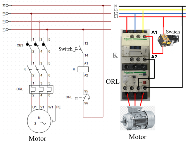
Simple contactor wiring diagram
– Working principle:
+ When we change the state of the switch from normally open to closed. The circuit will be closed, the coil is now energized, so the main contacts of the contactor will close. At this time, the motor receives energy from the three-phase power source and starts to work.
+ When the switch turns from closed to open, the circuit will open. The coil loses power, so the main contact of the contactor returns to the open state. The power circuit is open, so the motor stops working.
+ If the motor is overloaded, in a short time the thermal relay will change the state of its contacts. The normally closed contact of the thermal relay opens to de-energize the coil, causing the contactor to open. The motor stops rotating and the circuit shows an overload error.
7. Frequently asked questions about contactor
7.1 What is the difference between AC and DC contactors
+ DC contactor uses a small DC voltage of 24V, 48V, so it is safe to use for installers. Meanwhile AC contactor uses voltage 220V, 380V AC.
+ The electromagnetic core of the AC contactor is made of steel sheets to limit the loss from the eddy current. In DC contactor, soft steel block is used.
+ The electromagnetic core of AC contactor is usually E-shaped, while in DC contactor is usually U-shaped.
+ At the AC contactor there is a short circuit circle at the end of the stationary core. To help eliminate vibration and interference from the electromagnet coil.
+ AC contactor has a high starting current, with a maximum operating frequency of 600 times/hour. Contactor DC with a maximum frequency of 1200 times/hour.
7.2 What is the difference between a contactor and a relay
If anyone has known contactors, they must also know that a device with similar principles and functions is a relay. This means that the relay also includes a coil and a contact, when the coil is energized the contact changes state.
However, it is not possible to replace the relay for the contactor for the following reasons:
+ Load capacity: Relay is usually designed with a load carrying capacity of less than 10A. Meanwhile, contactors are used for loads up to several thousand Amperes.
+ Auxiliary contacts: Contactors are always designed with auxiliary contacts. Auxiliary contact used in the control circuit, to control itself or control the indicator lights.
+ Arc extinguishing system: In large capacity contactors equipped with arc extinguishing system. Relays are used for small and medium loads, so arcing is less of a concern. For relays, arcs are suppressed by adding on the circuit by simple components such as capacitors and resistors.
+ Overload protection function: In three-phase motor control applications, contactors are often combined with thermal relays. When the motor is overloaded, the thermal relay will trip the control circuit. Therefore disconnect the power from the motor.
7.3 How to check the contactor
During use, the contactor cannot avoid damage that makes the circuit not work properly. Therefore contactor need to be checked for maintenance and replacement
How to check contactor
– We will use VOM meter to check contactor
+ Check the coil: Adjust the meter to the resistance scale to measure the resistance of the coil. When the coil is in good working order, the meter needle will show a resistance value from a few hundred to a few thousand Ohm.
+ Measure the operation of the contact: in the normal state, when we measure the resistance of each pair of main contacts (L1, T1; L2, T2; L3, T3). Then the meter hand will not move (resistance is extremely large). When we press on the front of the contactor, the VOM needle shows 0 Ohm.
Same for the auxiliary contact, but for the normally closed contact, in the normal state the needle indicates 0 Ohm. When pressing the front of the contactor the meter needle does not move
8. Calculation for choosing magnetic starter
Assume that the contactor controls the motor switch with a capacity of 6kW, a voltage of 380V, and cosφ is chosen to be 0.85. Magnetic start selection will include contactor and thermal relay selection.
First we will calculate the rating of the motor based on the capacity:
P = √3.UICosφ
<=> I = P/(√3.UCosφ)
<=> I = 6/(√3x380x085)
<=> I = 10.8A
– Calculation to choose contactor
=> Rated current of contactor: IMC = (1.2 – 1.5).I
=> IMC = 1.5 x I = 16A
*** Relatively, we can quickly calculate the rated current of the contactor by the formula:
IMC = 3P
=> IMC = 3 x 6 = 18A
Then we can choose a contactor with a rated current of 18A.
– How to choose thermal relay
The thermal relay allows the operating current to be adjusted within a certain range. The current is regulated by the knob on the thermal relay.
For the motor in this case we will choose the thermal relay 16 – 22A.
In case if the motor has lost parameters, we can use the meter to measure the current while the motor is rotating. At this time, the thermal relay will select equal to the measured value plus 10% (or 1.1 times).
>>> Xem thêm