In this post we will analyze 4 single phase contactor wiring diagram. What is the advantage of single phase contactor and what is it used for?
Why use 2 pole contactor
Single-phase contactor (2 pole contactor) is a widely used instrument in control applications of single phase electrical equipment. With the advantage of being compact, easy to wire, cheaper than three phase contactor with the same capacity.
Single-phase contactor is also used to replace conventional switches and sockets to increase current capacity. Because the contactor is controlled by voltage, it is widely used in remote control applications for switching power circuits.
The symbol of a single-phase contactor in an electrical circuit is as shown below. The coil acts as an electromagnet creating a force of attraction to close the contact. The most common single-phase contactor coil is 220V AC. The contact is a direct load switching device, capable of allowing a large load current to pass through.
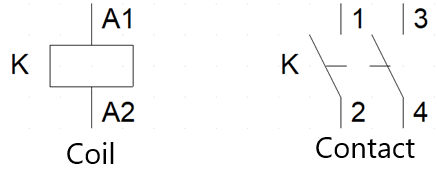
Symbol of single phase contactor
4 single phase contactor wiring diagram
1. AC motor control circuit using switch
Conventional switches can only control 1 phase (L or N) and have a small capacity. So they are commonly used in control circuits.
Using a single-phase contactor will disconnect both L and N wires, so it will be safer for users. The rated operating current of single phase contactor is up to 60A. So it is enough to drive large power single phase loads.
– AC motor control circuit wiring diagram using single phase contactor as shown below. The circuit on the left is visually drawn based on the actual device. And the circuit on the right is the schematic diagram of the circuit.
+ One terminal of the contactor’s coil is connected to the power supply (N), the other terminal is connected to the power supply (L) through a 2-position switch.
+ The top of the main contact is connected to the 220V power supply, the bottom of the contact is connected to a single-phase motor or 2-wire single-phase electrical equipment.
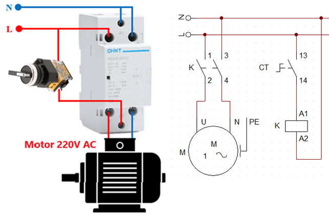
Circuit diagram using 2 position switch
Working principle:
+ In the normal state the switch is open, coil K is not energized. The contact will be in the open state, the motor will not work.
+ When there is a force acting to make the 2-position switch closed, the coil K is energized. Generate electromagnetic force to attract contact, change the state of contact from open to closed state. Current flows from the power supply through the contacts to the motor.
+ When the switch opens, the coil is disconnected. Thanks to the force of the spring the contact now returns to its original position. Therefore, the contact will be in the open state and the motor will stop working.
2. Remote control circuit using smart switch
Smart switches, remote control switches are more and more popular. Because it has the advantages of being cheap, convenient, and multi-functional. The output of these switches is a relay output, the maximum current is from 10 to 15A. Therefore, it is only suitable for controlling lights, fans, and small pumps.
Smart switches have many types such as switches controlled by RF waves, Bluetooth, SMS, wifi. When combined with a single-phase contactor, it will be possible to control large-capacity electrical appliances such as induction cookers, air conditioners, refrigerators, and motors.
Single phase contactor wiring diagram with smart switch is drawn as follows:
+ The input of the smart switch connects to 220V AC, the output connects to two terminals of the contactor coil. When connecting the input to the power supply, we do not need to define the L wire as in the circuit that uses a smart switch to directly control the load.
+ The two upper terminals of the contact are connected to the AC source and the two lower terminals are directly connected to the load.
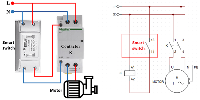
Wiring diagram of contactor with smart switch
Working principle:
Looking at the schematic diagram of this circuit, we see that the circuit principle works similarly to the 2-position switch circuit.
+ When the smart switch has not received the control command, the internal relay contact opens. Therefore, the main contact of the contactor is also open, so the motor does not rotate.
+ When the smart switch receives the command to turn on the device, the relay contact in the switch closes. The contactor coil is energized so its contact is closed. Single phase motor starts to rotate.
3. Control circuit using push button
The circuit using a 2-position switch has the advantage of being simple, but the disadvantage is that when the power is lost, the circuit will be in a standby state. When power is restored, the device will continue to operate. This will be very dangerous if the user forgets to turn off the device, which can lead to fire or electric shock.
Therefore, in industrial electrical cabinets, people will prioritize using 2 push buttons instead of using a 2 position switch. Because the single-phase contactor has no auxiliary contacts, we will use an additional 220V relay to keep the circuit closed after removing the button.
The circuit diagram is designed as shown below. Coil contactor 1 phase and relay connected in series with two push buttons ON and OFF. The normally open contact of the relay will be connected in parallel with the ON push button. The contactor contacts are connected directly to the load.
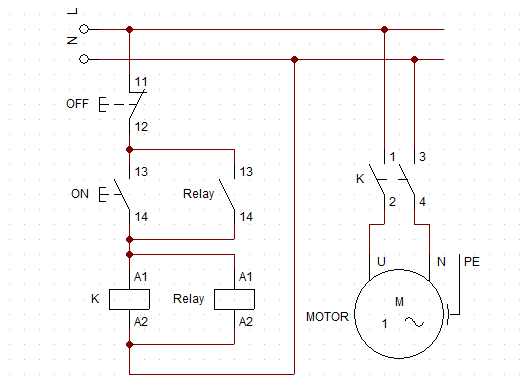
Single phase contactor wiring diagram with push button
Working principle of the circuit:
+ When the ON button is pressed, the control circuit is closed. The coils of contactor K and relay are both energized, so their contacts change state. At this point, the motor starts working and the relay contact closes. So after the ON button opens, current will pass through the relay contact, the circuit is still closed.
+ When the OFF button is pressed, the control circuit is open. The coils of contactor K and relay are disconnected from the power supply, so the motor stops working. At the same time, the relay’s contact opens, so after the OFF button is released, the motor will not run again.
Similar to case of power failure, after power failure. The user must press the ON button to get the motor running again. Safety circuit for users and electrical equipment.
4. Reversing single phase motor
A single-phase motor consists of two windings: the running coil and the starter coil. There will be 2 wires connected together to form a common point, so the motor will have 3 output wires. The starting coil and the running coil will have different resistance values. Specifically, the running coil resistance is smaller than the starter coil. We can determine these two coils using a VOM meter to measure the resistance of each winding.
Normally, people will connect the running coil in series with the capacitor and connect to the 220V source. The starter coil will connect directly to the power supply.
When reversing the motor, we connect the starter coil in series with the capacitor and connect to the power source. The running coil will be connected to a single-phase power supply.
The schematic diagram is as shown below.
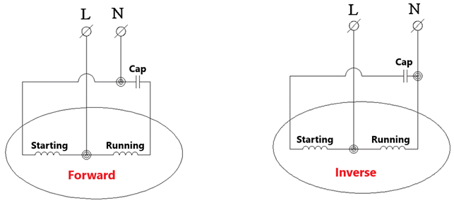
The principle of reversing a single-phase motor with 3 output wires
The wiring diagram below uses a single-phase contactor to reverse the direction of a single-phase motor.
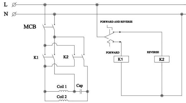
Single phase motor reversing circuit
Working principle of reverse circuit:
+ When the forward switch is turned on, contactor K1 is powered. Capacitor in series with coil 2 and connected to power supply (N). The common wire is connected to the power supply (L) and coil 1 is connected to the power supply in parallel. The AC motor will run in the forward direction
+ When the reverse switch is turned on, contactor K2 is energized. Capacitor in series with coil 1 and connected to power supply (N). Coil 2 is connected in parallel with the source. The motor will run in the opposite direction
>>> Related posts:
What is contactor – The best detailed article about contactor