Today’s article will cover the three-phase PWM rectifier circuit, including the circuit diagram, operating principle, and advantages of using pulse width modulation.
What is 3 phase PWM Rectifier?
PWM Rectifier is a method of converting AC voltage into DC, using pulse width modulation (pwm) to control forced commutation electronic semiconductor switches. Conventional PWM converters are used in distributed power generation applications, wind turbines, fuel cells and windmills.
1. PWM rectifier circuit diagram
This circuit utilizes 6 semiconductor switches known as IGBTs to execute high-frequency switching. The pulse frequency driving the IGBTs is determined by the carrier frequency – the higher the frequency, the more stable the output voltage. However, increasing the frequency also raises the losses on the IGBTs, leading to an increase in their temperature.
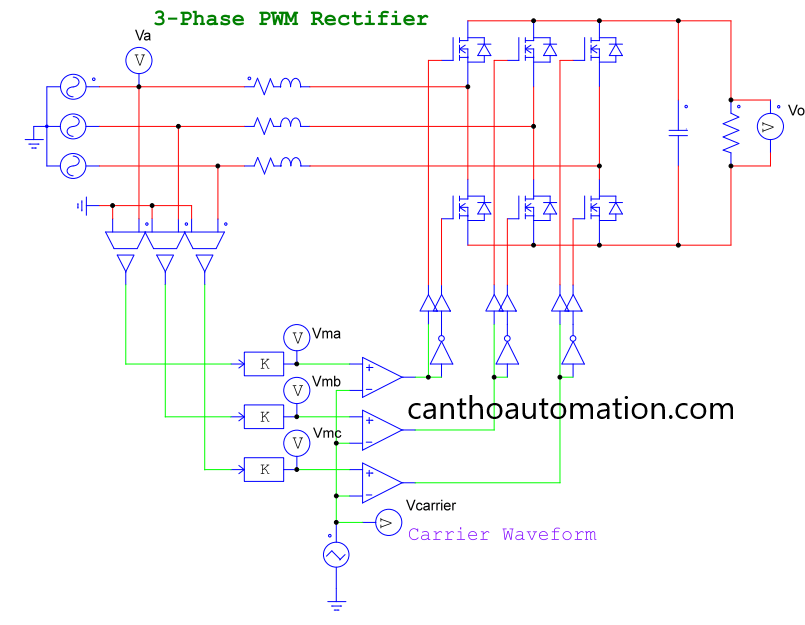
PWM Rectifier circuit diagram
2. Working principle
Remember the following information:
The G terminal of the lower IGBTs is connected to an inverting gate to prevent the upper and lower IGBTs from conducting at the same time, thus avoiding short circuits.
The high-amplitude sine source voltage (Va, Vb, Vc) is reduced to a sine signal with a constant frequency but smaller amplitude (Vma, Vmb, Vmc). This voltage signal will then be compared with a reference wave.
+ When the voltage Vm is greater than the voltage of the carrier wave, the output voltage of the comparator is positive.
+ When the voltage Vm is smaller than the voltage of the carrier wave, the output voltage of the comparator is 0V.
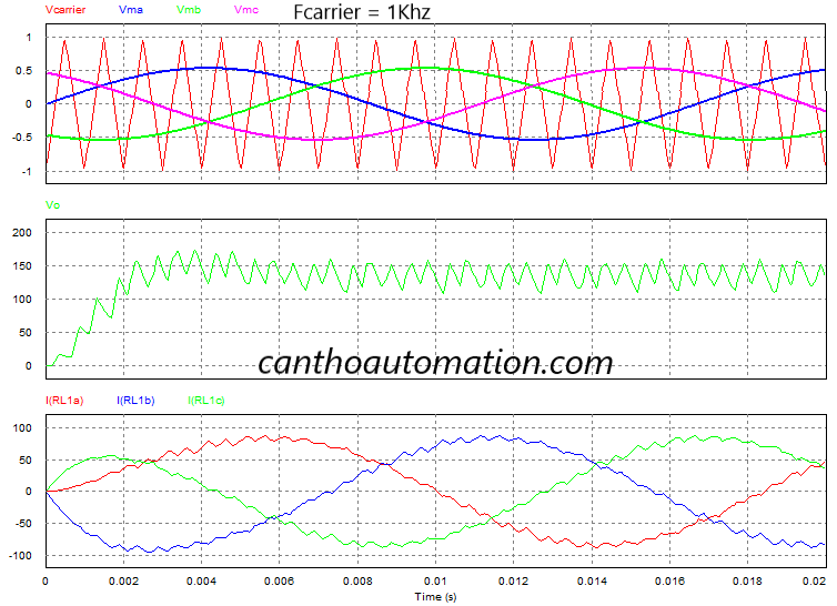
Output voltage waveform with frequency carrier = 1Khz
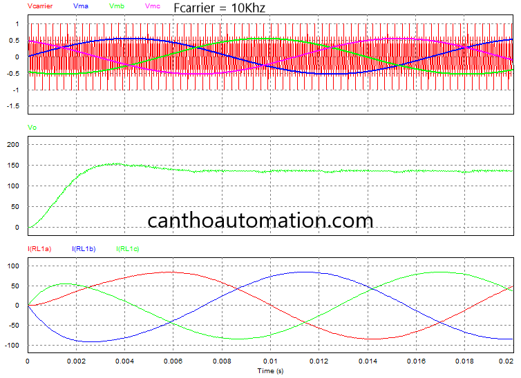
Output voltage waveform with frequency carrier = 10Khz
Advantages and applications
The major advantage of using the pulse width modulation technique is the reduction of higher order harmonics. It also makes it possible to control the magnitude of the output voltage, and improve the power factor by forcing the switches to follow the input voltage waveform.
In contrast to diode bridge rectifiers, PWM rectifiers achieve bidirectional power flow. In frequency converters this property makes it possible to perform regenerative braking
>>> Related articles:
Three phase full wave controlled rectifier (3 Examples)