Working principle of three phase full wave controlled rectifier circuit. Designing control circuit to generate trigger pulse; the output waveform of rectifier circuit in three cases.
1. Definition, Construction
Three phase full wave controlled rectifier is a circuit that uses six thyristors to convert ac input power supply into dc output power across the load. Thanks to the control to turn on and turn off the thyristors, we can change the average value of DC output voltage. Three-phase controlled rectifiers are extensively used in high power variable speed industrial dc drives.
The input three-phase power supply does not use a neutral wire. Assume that this is a standard three-phase power supply. It consisting of three different ac signals, and It is 120 degrees out of phase. The thyristors are connected in three pairs shown below.
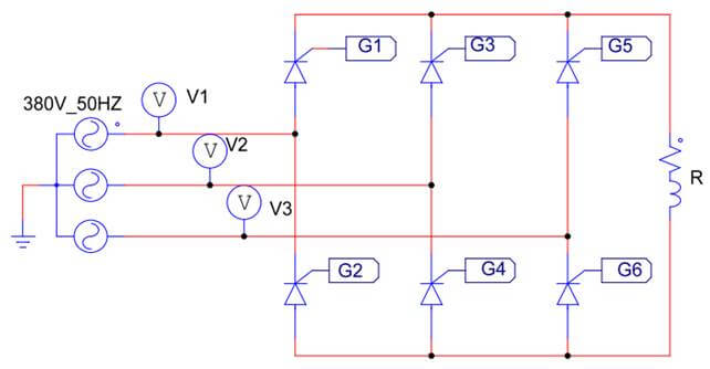
What is 3-phase full wave controlled rectifier
The series characteristic of this rectifier produces a dc voltage twice the value of the half-wave rectifier. It provide higher dc output voltage and higher dc output power. Filtering requirements are simplified for smoothing out load voltage and load current.
2. Three phase full wave controlled rectifier circuit
The schematic diagram of the power circuit and the control circuit is designed as shown below. We will learn how this circuit works.
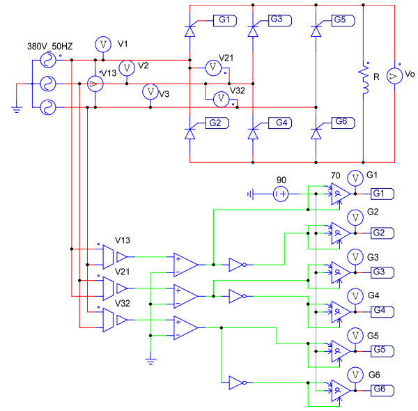
Three phase full wave controlled rectifier circuit
2.1 Designing control circuit on Psim software
In three phase fully controlled rectifier, the control signal must be synchronized with the supply voltage.
Firstly, we need to convert the input voltage to the control voltage by the Voltage Sensor block. Then we will use the Comparator block to convert the output Analog signal into a digital signal.
Next, this signal pulse is applied to the Alpha control block. The alpha controller is used to control the delay angle of the thyristor bridge. When the signal is High, this block will delay a preset amount of time (alpha), and it will output a pulse to trigger the SCR.
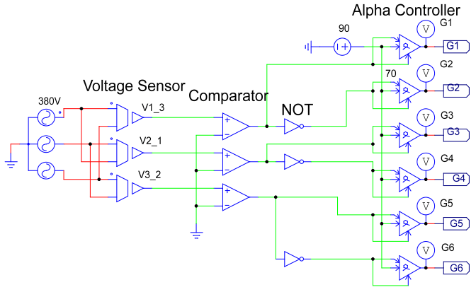
Control circuit of three phase full wave controlled rectifier
2.2 Control signals of 3-phase full wave controlled rectifier
The principle of generating an SCR trigger pulse in a three-phase bridge rectifier is quite complicated. The circuit has some rules:
+ Two thyristors of a pair will not conduct at the same time because it will lead to a short circuit
+ To switch the SCR to the conduction state, a control pulse signal must be applied to a pair of SCRs. During one cycle, the thyristors will conduct in the order: D4 + D1; D1 + D6; D6 + D3; D3 + D2; D2 + D5; D5 + D4.
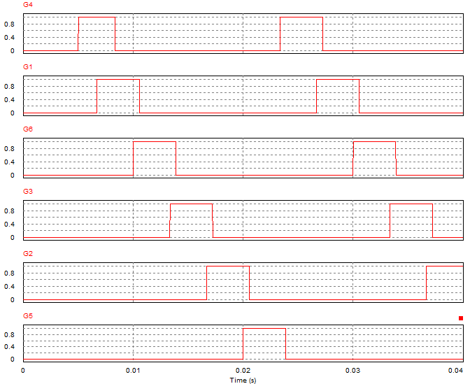
Control signals of 3-phase full converter
The distance between two control pulse signals is 60 degrees. Therefore we can also use the control pulse as a pulse train or a pulse with sufficiently large pulse width. In this article, we use a signal with a pulse width is 70 degrees shown above.
2.3 Output waveform
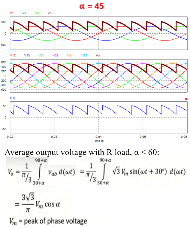
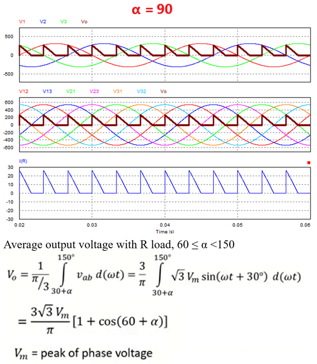
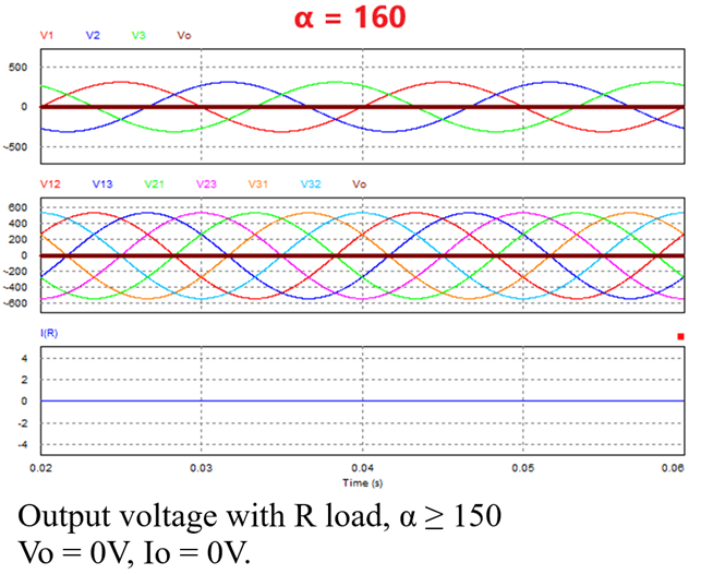
Depending on the trigger angle α, the output waveform will be different. The smaller the trigger angle α, the larger the average output voltage. When the thyristor conducts, the output voltage is the same as the line to line supply voltage. We will consider three cases:
a. 0 ≤ α < 60
In the case of trigger angle α < 60, the output current is continuous (IR is always greater than zero).
b. 60 ≤ α < 150
In the case of excitation angle 60 ≤ α < 150, the output current is interrupted (IR is not always greater than zero).
c. α ≥ 150
When the trigger angle α ≥ 150, the thyristor cannot be controlled. The output voltage and current are zero.
>>> Related posts:
3 phase half wave controlled rectifier (2 circuits)
3 phase full wave rectifier circuit diagram (4 circuits)
3 phase half wave rectifier circuit (4 circuits)
>>> See also: Three phase fully controlled converter – Power Electronics & Drives