A sequential motor control circuit is a circuit that controls the motors to operate in sequence. One motor cannot start until some other motor is running.
For example, Sequential Control is used by machines such as hydraulic presses. The pressure pump operates before the hydraulic valves can be used. Or because some air conditioning systems require the fan to operate before the compressor starts. Let’s learn about some of the following sequential circuits.
>>> See Also:
4 circuit diagram of star-delta starter
What is contactor? Best article about contactor
How to reverse a 3 phase motor with Switch, PLC, Inverter (5 circuits)
Dynamic braking and reverse braking circuit of induction motor
1. Sequential control circuit using push button
– Wiring diagram
Sequential circuit diagram using 3 sets of ON and OFF buttons to control the motor to run and stop.
+ In the power circuit, each motor is connected to a separate contactor. And is protected from overload by thermal relay.
+ Set of push buttons ON1, OFF1 to control motor 1.
+ Set of push buttons ON2, OFF2 in series with ON1 push button to control motor 2
+ Two push buttons ON3, OFF3 in series with push buttons ON1, ON2 to control motor 3.
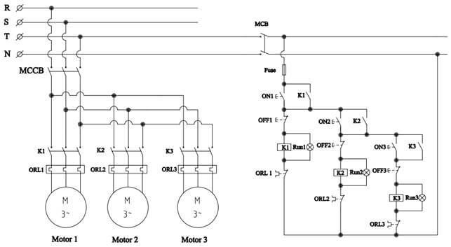
Sequential circuit wiring diagram using push button
– Working principle
Motor 2 and motor 3 can only work when motor 1 is running, and motor 3 can only run when motor 2 is running.
+ When ON1 is pressed, contactor K1 is energized, changing the state of the contacts of the contactor. The main contact of contactor K closes to supply power to motor 1. At the same time, the normally open contact K1 closes to keep the circuit closed after the ON1 push button returns to the open state.
+ Contact K1 is closed so motor 2 is ready to operate when we press the ON2 button.
+ Similarly, when motor 2 is operating, if we press the ON3 button, motor 3 will run immediately.
+ We press OFF3 button to stop motor 3, press OFF2 to stop motor 2 and motor 3. And when we press OFF1 button to stop motor 1, 2, 3.
2. Control circuit using timer
– Wiring diagram of a sequential motor control circuit using timer
+ Wiring diagram for sequential control circuit that switches automatically using only one set of ON, OFF push buttons.
+ The coil of timer T1 will connect the coil of contactor K2 in parallel. And timer coil T1 is in series with normally closed contact K2. Therefore, when contactor K2 is energized, the timer will be disconnected from the power supply but contactor K1 is still active.
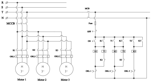
Sequence circuit wiring diagram works automatically
– Working Principle:
+ When we press the ON button, the contact K1 closes, so motor 1 works. At the same time, the coil of Timer T1 is also energized and starts counting time.
+ When the Timer counts to the preset time, the normally open contact T1 closes to supply power to contactor K2, then motor 2 works.
The normally closed contact K2 opens to de-energize the Timer T1 coil. At the same time, the normally open contact K2 closes to keep contactor K2 operating. And timer coil T2 is also energized and starts counting.
+ When timer T2 counts to the preset time, contactor K3 is energized. Then motor 3 will operate and timer coil T2 is disconnected from the power supply.
Refer to the simulation video about the sequence control circuit using timer
3. Sequential motor control circuit using PLC
3.1 Wiring diagram
The wiring diagram using PLC is as follows:
+ The ON button is connected to input X0, and the OFF button is connected to input X1. Unlike the above two circuits, for PLC circuits, people often use the OFF button in normally open instead of normally closed.
+ Outputs Y0, Y1, Y2 of PLC connect to coil of contactor K1, K2, K3.
+ The normally closed contact of the thermal relay will be connected in series with the contactor coil.
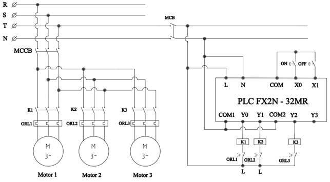
Diagram of a sequence motor control circuit by PLC
3.2 Sequential control circuit program on PLC
The operation of the PLC program is as follows:
+ When the ON button is pressed, X0 turns on, so the circuit is closed, the output Y0 will activate. At this time, the contactor coil K1 is energized, so motor 1 works. At the same time timer T1 starts to count the time.
+ When T1 counts to 10s, output Y1 is activated and timer T2 starts counting. When Y1 turns on, contact K2 closes so motor 2 operates.
+ Similarly, when T2 counts to the preset time (10s), the PLC will activate output Y2, motor 3 will start working.
+ When we press X1, Y0 will be disabled, so output Y1 and Y2 turn off. The operation of the program returns to the initial state.
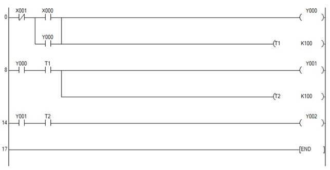
Sequence control program on PLC