This article will show you how to use Arduino Uno control servo with photoresistor in the simplest way. Understand the basics of servo motor and photoresistor operation. Explain the connection diagram and program on Arduino.
1. Component List
+ 1 Arduino Uno R3
+ 1 Positional Micro Servo
+ 1 Resistor 2.2 kΩ
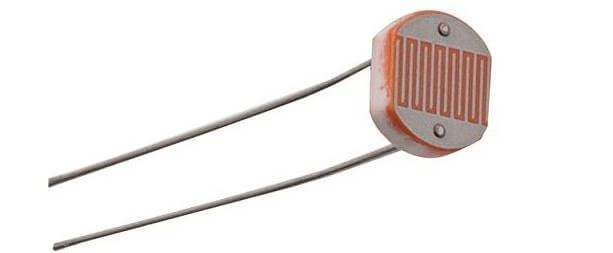
+ Photoresistor (LDR)
1.1 Photoristor
A photoresistor is a type of light sensor. When the light intensity changes, the resistance value on this sensor will change.
+ When it is dark, the photoresistor has a value of up to several hundred MΩ.
+ When it’s bright, the photoresistor’s value drops to a few hundred Ω.
– Working prrinciple:
Photoresistor made of semiconductor material that is photosensitive. They do not have any PN junction. When light falls on the photosensitive material (or on the Photoresistor), the valence electrons absorb the light energy and break free from the nucleus to become free electrons. These electrons lead to flow of current when an external force like an electric field is applied.
What is photoresistor
– Application:
Most common application in the circuits of automatic street lights, and other consumer items like light meter, light sensor etc. In the example of this article, we will use Arduino Uno to control the servo motor with a photoresistor.
For the Arduino to measure the change in the resistance of the photoresistor, we will use a voltage divider circuit. In this configuration, the voltage output (Vout) increases as light increases.
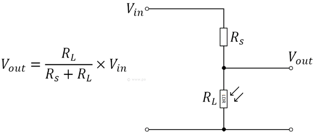
Voltage divider circuit using photoresistor
1.2 RC Servo
A servo motor is a type of DC motor that can rotate with great precision. Normally this type of motor consists of a control circuit that provides feedback on the current position of the motor shaft, this feedback allows the servo motors to rotate with great precision.
– Servo motor consists of three parts:
+ Controlled device
+ Output sensor
+ Feedback system
– Working Principle
It is a closed-loop system where it uses a positive feedback system to control motion and the final position of the shaft. Here the device is controlled by a feedback signal generated by comparing the output signal and reference input signal.
– Servo motor control
All RC motors have three wires coming out of them. Out of which two will be used for Supply (positive and negative) and one will be used for the control signal that is to be sent from the MCU. The MCU will output a pulse that can change the ON and OFF time (PWM).
Servo motor can turn 90 degrees in either direction forming its neutral position. The servo motor expects to see a pulse every 20 milliseconds (ms); the length of the pulse will determine how far the motor turns. For example, a 1.5ms pulse will make the motor turn to the 90° position. If the pulse is shorter than 1.5ms shaft moves to 0°. And if it is longer than 1.5ms, it will turn the servo to 180°.
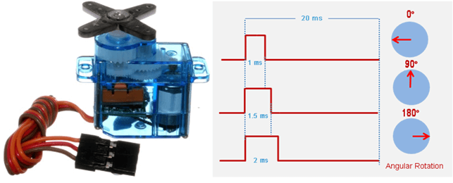
How to control servo motor
2. Arduino uno control servo with photoresistor
2.1 Wring
– Connecting Servo Motor to Arduino
+ The yellow wire of the motor connects to pin 9 Arduino. Pin 9 will output a PWM pulse that controls the position of the motor shaft.
+ The brown wire of the motor connects to the GND pin of the Arduino.
+ The red wire of the motor connects to the 5V source of the Arduino.
– Connect Arduino to photoresistor
+ Connect one pin of the photoresistor to the GND pin of the Arduino.
+ Connect one pin of the 2.2k resistor to the 5V pin of the Arduino.
+ Connect the other pin of the LDR connected with the 10kΩ resistor to the analog pin A0 of the Arduino.
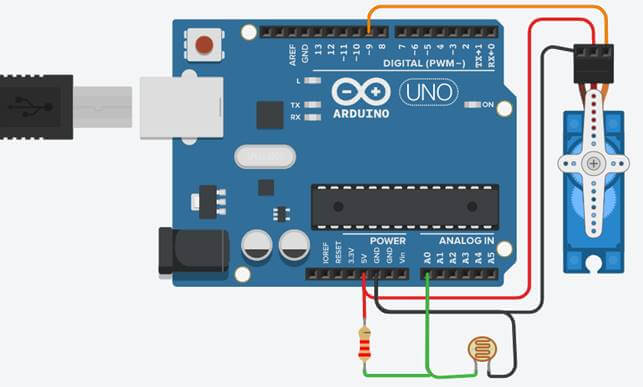
Arduino uno control servo with photoresistor
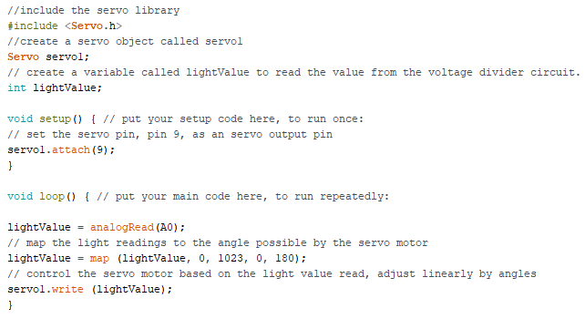
2.2 Arduino programming
The program below works as follows: The Arduino will read the value of the light sensor and change the position of the rotation angle of the Servo motor.
//include the servo library
#include <Servo.h>
//create a servo object called servo1
Servo servo1;
// create a variable called lightValue to read the value from the voltage divider.
int lightValue;
void setup() { // put your setup code here, to run once:
// initialize serial communication at 9600 bits per second:
Serial.begin(9600);
// set the servo pin, pin 9, as an servo output pin
servo1.attach(9);
}
void loop() { // put your main code here, to run repeatedly:
lightValue = analogRead(A0);
// map the light readings to the angle possible by the servo motor
lightValue = map (lightValue, 0, 1023, 0, 180);
// control the servo motor based on the light value read, adjust linearly by angles
servo1.write (lightValue);
// print out light sensor value
Serial.println(lightValue);
}
Programming arduino uno control servo
2.3 Video
Video simulation of circuit operation with Tinkercad software:
>>> See Also
How to reverse a 3 phase motor with Switch, PLC, Inverter (5 circuits)
4 wiring diagrams of star delta starter circuit
10 full bridge rectifier circuit diagrams – The Most Detailed Article
>>> Reference articles
What is Photoresistor – Symbol, Working, Types & Applications – circuitstoday.com
Servo Motor Basics, Working Principle & Theory – Circuit Digest