In today’s article, we will explore three applications of 12V DC motor forward and reverse circuit. We will also discuss the structure and operating principle of a DC motor.
How to Change the Direction of a DC Motor
The stator of a DC electric motor is typically composed of one or more pairs of permanent magnets or electromagnets. On the other hand, the rotor is made up of wound coils and is connected to a DC power source. Another crucial component of a DC motor is the rectifier, which is responsible for ensuring that the current flowing in the rotor remains constant in direction. Typically, this component consists of a commutator and a carbon brush that makes contact with the commutator.
A DC motor is responsible for converting direct current into mechanical work. It functions based on the principles of Lorentz Law. The stator of the DC motor generates a magnetic field. Once the rotor coils are energized and placed in the magnetic field, a force is produced that causes the rotor to rotate.
Reversing a DC motor is a simple process of changing the direction of the current by reversing the polarity of the voltage applied to the motor’s wires.
How to reverse a DC motor
12v dc motor forward and reverse circuit (three circuits)
1. Motor reversing circuit uses relay
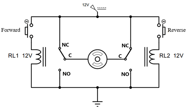
Circuit diagram of reversing dc motor using 2 relays
Working principle:
+ In the initial state, both ends of the motor wire are connected to the 12V source resulting in 0V potential difference across the motor wire. Consequently, the motor remains inactive.
+ When you press the forward button, the first relay coil is energized, which causes the relay to close. The active relay contact connects pin C (com) to pin NO. As a result, both ends of the motor receive a 12V voltage supply and the current flows from right to left of the motor. Consequently, the motor will start operating in the forward direction.
+ When the reverse button is pressed, relay 2 is activated, causing the normally open contact of the relay to switch to normally closed. This results in the motor being powered and the current flowing from left to right of the motor. As a result, the motor operates and rotates in the opposite direction.
Advantages and disadvantages
+ The circuit is simple and uses few components, making it easy to wire. It has a large capacity suitable for many DC motors, ranging from 10A – 25A.
+ The disadvantage of using a relay is that its switching speed is low because it uses mechanical contacts.
2. DC motor reversing circuit uses transistors
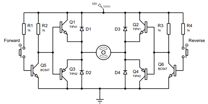
H-bridge circuit uses transistors
Working principle
+ The H-bridge circuit uses NPN transistors and PNP transistors connected in series on each side. The common terminal B is used to control the switching between the transistors. When one transistor conducts, the other one does not conduct, which makes it easy to control and prevent short circuits when both transistors conduct.
+ In the initial state, transistors Q5 and Q6 do not conduct. As a result, transistors Q3 and Q4 (TIP42) do not conduct, causing transistors Q1 and Q2 to also not conduct. This means that the motor remains unpowered and does not operate.
+ When the forward button is pressed, transistor Q5 (BC547) is activated. This pulls down the B pole of transistors Q1 and Q3 to 0V, which makes Q3 conduct and Q1 not conduct. As a result, transistor Q2 is immediately biased through resistor R3. The motor then rotates in the forward direction, with current flowing through Q2, the motor, and Q3.
+ When the reverse button is pressed, transistor Q6 conducts. Q4 and Q1 also conduct, leading the motor to rotate in the opposite direction.
+ The diodes D1, D2, D3, and D4 are connected in parallel with the transistor to eliminate the voltage generated from the motor when power is stopped.
Advantages and disadvantages
+ Advantages: The push buttons can be replaced with automatic control signals to achieve faster switching speed; provide short circuit protection.
+ Disadvantages: The circuit is relatively complex, and readers need a basic understanding of electronics to install a stable circuit.
3. 12v dc motor forward and reverse circuit using L298 motor driver
The motor driver module L298 is a widely available circuit that is cost-effective and user-friendly. It allows independent control of speed and direction of rotation for two DC motors.
In the circuit below, we use the rotation reverse function for only one motor while controlling its speed at maximum.
The motor reversing control circuit uses module L298
Operating principles:
+ The power circuit is powered by 12V DC, while the control circuit uses a 5V source.
+ The circuit uses Pins EN3 and EN4 to receive PWM signals that control the motor speed. However, in this particular circuit, we only use 0 or 5V signals on these pins. This means that the motor speed is always at its maximum. By changing the voltage level on these two pins, you can make the motor rotate in the opposite direction.
+ This module can control two motors simultaneously. However, in the picture above, we only use one motor connected to pins OUT3 and OUT4.
>>> Related articles:
Can a 3 phase motor run on single phase (3 ways)
L298n motor driver connection with arduino
Star delta control diagram with timer
>>> Video simulation