In this article, we will introduce the basics of variable frequency drive (VFD), the effect of the switching frequency has on vfd, and the pros and cons of increasing your carrier frequency in vfd.
What is carrier frequency in vfd?
VFD switching frequency refers to the rate at which the DC bus voltage is switched on and off during the pulse width modulation (PWM) process. The carrier frequency in the drive is usually between 1kHz and 15Khz. Choosing the carrier frequency is quite important, it will affect the noise level of the motor or the temperature of the inverter.
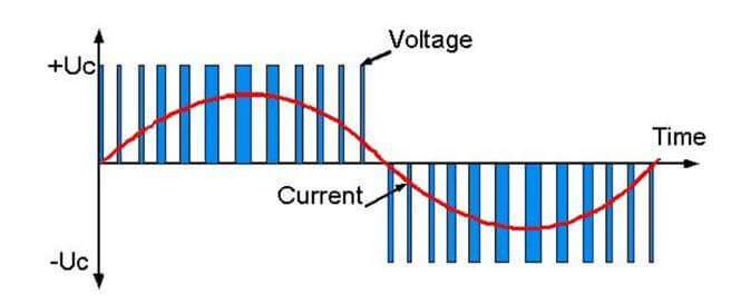
Output voltage and current waveform of the vfd
To make this issue clearer, we will briefly introduce the structure of VFD. Basically, the structure of the vfd consists of 3 parts:
+ Rectifier: Using a diode bridge circuit to convert the AC voltage of the grid into DC voltage.
+ Capacitor: The voltage waveform after passing through the rectifier is a DC voltage whose magnitude changes over time. The capacitor will help flatten and stabilize the DC voltage.
+ Inverter: Using semiconductor switches (IGBT) to convert DC voltage into AC voltage. The IGBTs will be controlled to create a waveform corresponding to a sine wave to help the motor operate. And the frequency used to switch the IGBT is called the carrier frequency.
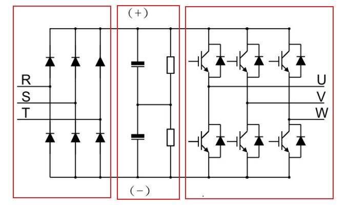
Basic structure of a VFD
Effect of carrier wave on vfd
1. How does carrier frequency affect vfd and motor?
The motor controlled by the drive will be affected by the high-frequency carrier wave, which will affect the noise level of the motor and the heating of the VFD.
+ There are a lot of advantages that come with increasing the switching frequency: ideal current waveform, little current harmonic wave, and motor noise.
One major benefit of this is that the resulting waveform is much cleaner, leading to reduced motor losses and higher overall efficiency of your motor. Moreover, the cleaner waveform also minimizes motor heating, which can increase the lifespan of your motor and result in less audible motor noise.
Finally, this effect is more pronounced at higher speeds. Therefore, a higher switching frequency allows for reaching a higher motor speed.
+ The disadvantages of high carrier frequency: increase switch loss, increase inverter temperature, and the impact on the output capacity.
The inverter needs to derate on high carrier frequency. At the same time, the leakage and electrical magnetic interference will increase. Applying low carrier frequency contradicts the above. Too low carrier frequency will cause unstable running, torque decreasing, and surge.
The manufacturer has set a reasonable carrier frequency when the inverter is in the factory. In general, users do not need to change the parameters. When the frequency use exceeds the default carrier frequency, the inverter needs to derate 20% for each additional 1k carrier frequency.
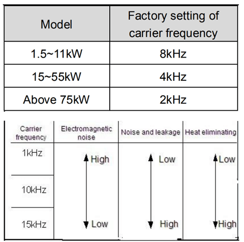
The relationship table of the motor type and carrier frequency
2. Affect Harmonic Distortion
Harmonic distortion occurs when the VFD converts AC power to a variable frequency output to the motor. Harmonics occur when transistors turn on and off rapidly at a rapid rate. Harmonic distortion in the drive can be reduced by increasing the operating speed of the IGBT to obtain a cleaner sine wave for better motor performance.
Harmonic Distortion (source: pumpsandsystems.com)
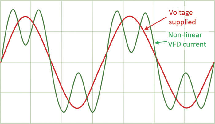
Non-linear loading refers to the situation where the current is not consumed in the same way as the voltage is supplied by the utility. This results in a “harmonic current” that contains multiples of the line frequency within the waveform. For a six-pulse drive, this includes the 5th, 7th, 11th, 13th, 17th and 19th harmonics. These harmonics typically range from 50-70 percent current harmonics, also known as total harmonic distortion current (THDi).
If this is the only loading present in a facility, the utility may classify it as a “harmonic rich” load and require the use of a harmonic mitigation device to resolve the issue. However, it was previously mentioned that VFDs (variable frequency drives) can help reduce kilowatt usage.
3. Output waveform of the inverter
As discussed earlier regarding the structure of an inverter, the output voltage generated by it is not pure 3-phase electricity. Instead, it is a DC Bus electricity that is pulsed to have the equivalent function used for 3-phase motors. Based on the type of the inverter, the pulse hashing control method differs, which leads to several different output types. The special inverter output also gives rise to some problems, which are mentioned below.
When an inverter is used to control a motor, it can optimize power savings by regulating the electrical pulses that control motor operation. Depending on the application, power consumption can be reduced by over 10% during installation.
Measuring the output voltage of a non-sine wave AC voltage can be difficult with cheap electronic meters. In such cases, it is recommended to open the monitor parameters on the inverter or use specialized meters that can accurately measure True RMS. By doing so, you can determine the exact voltage of the inverter’s output.
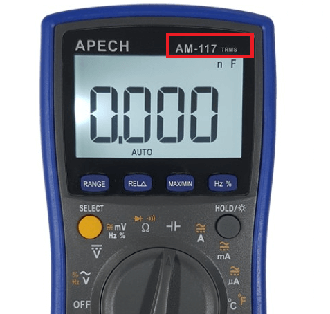
The meter precisely measures the voltage of the inverter output
The output voltage of the inverter is a waveform that functions similarly to a sine voltage. Due to this, the inverter can only be safely used with 3-phase motors. If used with other electrical equipment, it may cause damage to both the inverter and the equipment.
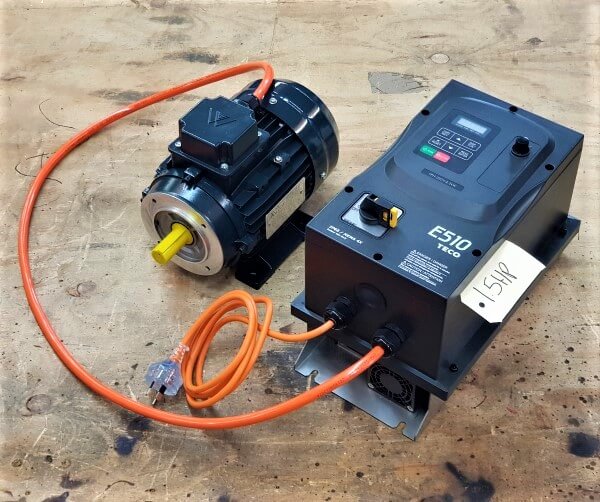
The inverter serves solely to control the motor.
>>> Related articles:
How to install and wire INVT inverter
Sequential motor control circuit (3 circuit diagrams)
Some star delta starter control circuits
>>> Reference videos (KEB America)