In the previous post, we learned about the speed control of a DC motor using Arduino. This article will guide another control method: L298n motor driver connection with Arduino. The advantage of this circuit is that it is cheap and can control two small DC motors independently.
L298N motor driver module
1. L298N Motor Driver Module
L298n motor driver connection with Arduino can control the direction and speed of two dc motors at the same time. Using the main IC is L298, which consists of two H-bridge transistors.
1.1 Specifications
– Supply voltage from 5 – 30V
– Maximum current for each motor is 2A
– Voltage of control signal: 5-7V
– Current of control signal required 0 – 36 mA
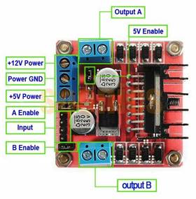
1.2 Pin functions
– Power Supply: From “Vs” pin the H-Bridge gets its power for driving the motors which can be 5 to 35V. “Vss” is used for driving the logic circuitry which can be 5 to 7V. And they both sink to a common ground named “GND”.
– Enable pin: ENA and ENB are used to turn the motors ON, OFF. The module usually comes with a jumper on these pins.
– Direction Control Pins: The IN1 and IN2 pins control the direction of the motor A, while IN3 and IN4 control the direction of the motor B.
– Output Pin: Output, Output connect with Motor1, Motor2
2. L298n motor driver connection with arduino
The figure below shows the speed control circuit diagram of two DC motors using the L298n driver with Arduino Uno R3.
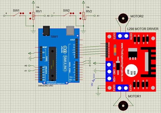
l298n motor driver connection with arduino
Connect pins IN1, IN2, IN3, and IN4 of L298 to pins 9, 10, 11, and 12 of Arduino. Pins 11 and 9 will output PWM pulses to control the speed; pins 10 and 12 will control the direction of motor rotation. Don’t forget to connect the GND of the L298 driver to the GND of the Arduino.
Note:
+ When the signal at pin IN2, IN4 is low: if the PWM pulse width at pin IN1, IN3 is larger, the speed is faster.
+ When the signal at pin IN2, IN4 is high: if the PWM pulse width at pin IN1, IN3 is larger, the speed is slower.
Pins 6 and 7 read the state of 2 reversing switches of two motors. Pins A0 and A1 read analog values from two potentiometers to control motor speed.
3. Arduino Programming
For example, controll the speed and direction of two independent DC motors. When the switch is in the open state, the motor rotates in the forward direction. Changing the potentionmeter value changes the motor speed. When the rotation control switch turns to the closed state, DC motor will stop for 0.5s and then reverse the motor rotation direction.
The Arduino program “l298n motor driver connection with arduino”
#define IN1 9
#define IN2 10
#define IN3 11
#define IN4 12
int speed1=0;
int speed2=0;
int direction1=0;
int direction2=0;
void setup()
{
// Set all the motor control pins to outputs
pinMode(IN1, OUTPUT);
pinMode(IN2, OUTPUT);
pinMode(IN3, OUTPUT);
pinMode(IN4, OUTPUT);
//configure pin 6, 7 as an input and enable the internal pull-up resistor
pinMode(6, INPUT_PULLUP);
pinMode(7, INPUT_PULLUP);
}
void loop()
{
// Read the values from the potentiometers (0 – 1023)
speed1=analogRead(A0);
speed2=analogRead(A1);
// Convert to range of 0-255 (duty cycle)
speed1=speed1/4;
speed2=speed2/4;
//********Controlling the dicrection and speed of DC Motor1 *********//
if( digitalRead(6)==0){ //Read the value of the direction switch
if( direction1 != digitalRead(6) ){
// Now turn off motors 500ms before reversing
digitalWrite(IN1, LOW);
digitalWrite(IN2, LOW);
delay(500);
direction1=0;
}
// Control speed and reverse direction
digitalWrite(IN2, LOW);
analogWrite(IN1,speed1);
}
if( digitalRead(6)==1){
if( direction1 != digitalRead(6) ){
// Now turn off motors 500ms before reversing
digitalWrite(IN1, LOW);
digitalWrite(IN2, LOW);
delay(500);
direction1=1;
}
// Control speed and forward direction
digitalWrite(IN2, HIGH);
analogWrite(IN1,speed1);
}
//********Controlling the dicrection and speed of DC Motor2 *********//
if( digitalRead(7)==0){ //Read the value of the direction switch
if( direction2 != digitalRead(7) ){
// Now turn off motors 500ms before reversing
digitalWrite(IN3, LOW);
digitalWrite(IN4, LOW);
delay(500);
direction2=0;
}
// Control speed and reverse direction
digitalWrite(IN4, LOW);
analogWrite(IN3,speed2);
}
if( digitalRead(7)==1){ //chạy nghịch
if( direction2 != digitalRead(7) ){
// Now turn off motors 500ms before reversing
digitalWrite(IN3, LOW);
digitalWrite(IN4, LOW);
delay(500);
direction2=1;
}
// Control speed and forward direction
digitalWrite(IN4, HIGH);
analogWrite(IN3,speed2);
}
}
>>> Simulation video of DC motor speed control circuit using L298N