Dynamic braking and reverse braking circuit diagrams in three phase induction motor. When the three phase motor is disconnected from the three phase power supply, the motor will start to decelerate until it reaches zero. The deceleration time depends on the inertia of the load.
Some applications require a 3-phase induction motor to decelerate rapidly, especially in conveyor control. Two methods are used to rapidly reduce the motor speed: mechanical braking and electric braking.
Mechanical brakes work on the principle of creating friction to keep the rotating shaft stationary. Therefore, the mechanical brake will generate heat and cause mechanical loss. In this article, we only learn about some types of electric brakes such as dynamic braking and reverse braking, regenerative braking.
1. Electric brake methods
The three-phase asynchronous motor works on the principle of electromagnetic induction. The three phase voltage applied to the motor stator creates a rotating magnetic field. The rotating magnetic field is the main cause of the force that rotates the motor rotor.
Dynamic braking is a method of rapidly reducing motor speed by creating a stationary magnetic field. By applying a DC voltage to the motor stator winding, a stationary magnetic field is generated to hold the motor rotor. The advantage of this circuit is that it reduces mechanical losses.
Reverse braking is a method of using motor reverse wiring to generate torque to quickly stop the motor. After the motor is disconnected from the supply voltage, the motor is wired to rotate in the opposite direction. We see the disadvantage of this circuit is that it generates a large current when the motor reverses. So this method is only suitable for small capacity motors.
Regenerative braking is commonly used in frequency converters. When the inverter turns off the output, the motor will act as a generator, the voltage on the motor returns to the DC Bus of the inverter. One will connect the DC Bus to a Brake resistor to dissipate the energy as heat. This method has the advantage of being efficient and is widely used in industrial circuits.
2. Dynamic braking circuit
The stationary magnetic field that is formed depends on the connection at the stator windings and the magnitude of the DC voltage applied to the stator.
The larger the DC voltage, the more current flows in the stator, so the voltage directly affects the braking torque. The current should not exceed the rated current of the motor windings.
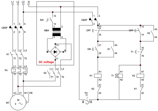
Circuit diagram of dynamic brake
+ When the SW switch is closed, the circuit provides a fast stop. If the SW switch is open, the deceleration time of the motor depends on the moment of inertia.
+ 220V AC voltage is rectified into DC power through diode bridge. DC voltage is applied to the motor windings through the contactor K2.
+ Push button ON, OFF controls the opening and closing of contact K1.
+ Coil K2 is in series with normally open contact of OFF push button and normally closed contact of timer T1. Therefore, coil K2 will be energized when we press the OFF button. Then the coil is de-energized after a period of time T1.
Dynamic braking circuit
Principle of dynamic braking circuit:
+ When the ON button is pressed, coil K1 is energized, the main contact of contactor K1 is closed. Three-phase voltage is applied to the motor so the motor starts to work.
+ When the OFF button is pressed, the contact K1 returns to the original state, the motor stops working. At the same time contactor K2 is energized, so DC voltage is applied to the motor windings. And timer coil T1 is also energized so it starts counting time.
The DC voltage applied to the coil will generate a stationary magnetic field, keeping the motor’s rotor in check. The motor stops quickly.
+ After the timer counts to the preset time, the normally closed contact of the timer opens and disconnects coil K2. The circuit returns to its original state.
Refer to the simulation video of the dynamic brake circuit
3. Reverse brake circuit
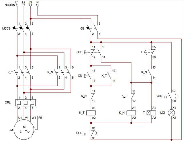
Reverse brake circuit diagram
+ The dynamic circuit of the reverse brake circuit is actually the reversing circuit of the 3-phase motor. When the K_N contact closes, two of the wires are switched.
+ Two push buttons ON, OFF control closing, opening the control circuit.
+ Normally open contact of OFF button connected to coil K_N.
+ Timer T is used to adjust the time the motor rotates in the reverse direction.
+ Thermal relay used to protect motor overload.
Reverse brake circuit diagram
Working principle of reverse braking circuit:
The principle of reverse braking circuit is similar to dynamic braking circuit:
+ When the ON button is pressed, the K_T contact is closed. At this time, a three-phase voltage is applied to the motor, so the motor rotates in the forward direction.
+ When the OFF button is pressed, the K_T contact opens. And the motor is disconnected from the powerline. Immediately contact K_N close , motor will rotate in the opposite direction.
At the same time, the timer coil is also energized, starting to count the time.
+ When the timer counts to the preset time, the T contact opens and disconnects the K_N coil.
*** Note that the purpose of the circuit is to control a quick stop of the motor. If the motor rotates in the opposite direction is undesirable. So contactor K_N should not be closed for too long, which will lead to the motor rotating in the inversing direction.
However, if the contactor K_N closes time is too short, there is not enough torque to stop the motor. After braking the motor can continue to rotate in the forward direction.
Refer to the video simulating the operation of the reverse brake circuit
>>> Xem thêm:
Working principle of 4 star delta starter circuit diagrams
Learning about bridge rectifier circuits (10 circuits)