In this article we will learn about stop start contactor wiring diagram (3 circuits) for controlling three phase motor. Advantages and disadvantages of the contactor control circuit using push buttons compared to the switch.
Comparison of contactor control circuit by switch and push button
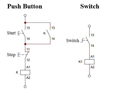
The circuit diagram using 2 push buttons and a switch to control the opening and closing of a contactor is drawn as shown below.

Difference between circuit using push button and switch
– The circuit uses a 2-position switch
+ Advantages: this is the simplest circuit to control the contactor. The circuit diagram and operating principle are very simple: when the switch is closed, the contactor is energized. When the switch is open, the circuit is open, the contactor is disconnected from the power supply.
The disadvantage of this circuit is when the motor is running. Assuming the power is suddenly lost, the motor will stop. If the switch is not set to normally open, the circuit will be in standby mode. When power is restored, the motor continues to rotate. This is dangerous for the user and the output load if the switch is forgotten to return to the open position during a power failure.
– Start stop contactor wiring diagram using push button
+ The advantage of the circuit using 2 push buttons is that when the circuit is running, if there is a power failure, the circuit will immediately return to the original state. When power is restored, the motor will still stop. Because of this advantage, the circuit using the push button is widely applied in industrial electrical cabinets.
+ The disadvantage of this circuit is that it is more expensive, the circuit is more complicated than the circuit using a switch. And it is required to use auxiliary contact of the contactor or we can use a 220V relay to replace the auxiliary contact.
3 stop start contactor wiring diagram using switches and pushbuttons
1. The circuit uses 2 Position Rotary Switches
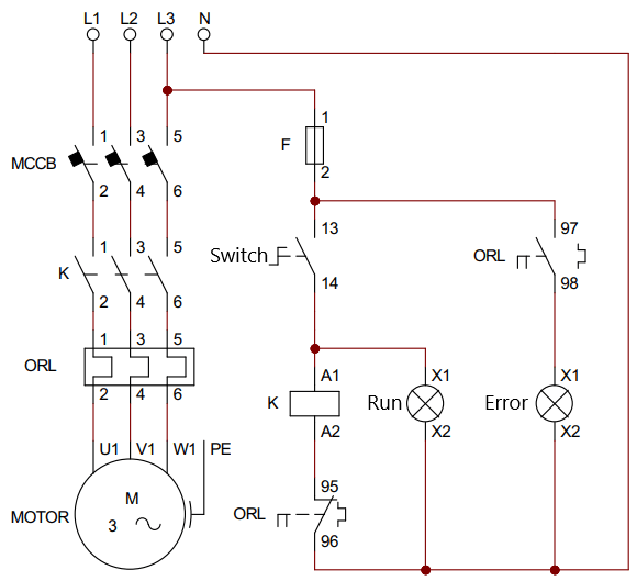
* Wiring diagram of running and stopping contactor by switch

Controlling the contactor with 2 position rotary switch
– Power circuit
Power circuit to control switch of 3-phase motor includes: Circuit Breaker (CB), magnetic starter, thermal relay. In which CB is a device to manually turn on and off the power supply and to protect the short circuit of the power circuit. Magnetic starters use 3 main contacts to connect and disconnect 3-phase motors from the mains.
+ Magnetic starter includes contactor in series with thermal relay.
+ Three wires of the motor will connect to the other terminal of the thermal relay.
+ The upper contact of the contactor connects to the power supply through the CB.
– Control circuit:
+ The control circuit uses the switch in series with the contactor coil, and in series with the normally closed contact (95 96) of the thermal relay. Fuse in series with the whole circuit for short circuit and overload protection of the control circuit.
+ Run indicator is connected in parallel with the contactor coil. When the contactor is energized, the light is on, when the contactor is not energized, the light is off.
+ Fault indicator in series with normally open contact (97 98) of thermal relay. Lights up when the thermal relay is activated, indicating overload in the motor.
* Working principle
+First we will turn on 3 phase MCCB. In the normal state, the switch is in the open state, and the control circuit is open.
+ When we turn the switch to the closed state, the control circuit is closed. At this time, current will flow through the contactor coil K. The contactor coil becomes an electromagnet that attracts the moving contacts, changing the contact state K from open to closed.
When the K contact is closed, the power circuit will be closed, so the motor is supplied with 3-phase power and the motor starts to work.
+ When we turn the switch to the normally open position, the contactor coil loses power. Thanks to the force of the internal spring, the contact is returned to its original position. Contact K from the closed state becomes open, so the motor loses power and will stop rotating.
2. The circuit uses two push buttons
– Wiring diagram
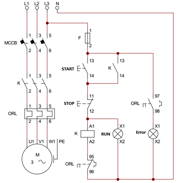
+ The 2-position switch is replaced by a normally open button Start in series with a normally closed button Stop.
+ Auxiliary contact K is connected in parallel with the Start button to replace this button after it returns to its original state.

Stop start contactor wiring diagram using two push buttons
– Principle:
+ When we press the Start button, the control circuit is closed and the contactor is energized. The main contact and the auxiliary contact of contactor K will close. And the Motor is supplied with 3 phase power and starts to rotate.
+ After releasing the Start button to return to the open state, current flows through the auxiliary contact K, through the coil K.
+ When we press the Stop button, the control circuit is open. So the contactor loses power, causing the motor to lose connection to the 3-phase voltage.
+ When the motor is overloaded, the current through the thermal relay is higher than the rated current. The bimetallic strip inside the thermal relay gets heated, changing its contact state.
+ The ORL contact (95 96) switches from normally closed to normally open, so contactor coil K is no longer energized. At the same time, the ORL contact (97 98) is closed, the Error indicator light is on.
Refer to the video about the contactor wiring diagram using two push buttons– Galco TV
3. Control circuit in 2 positions
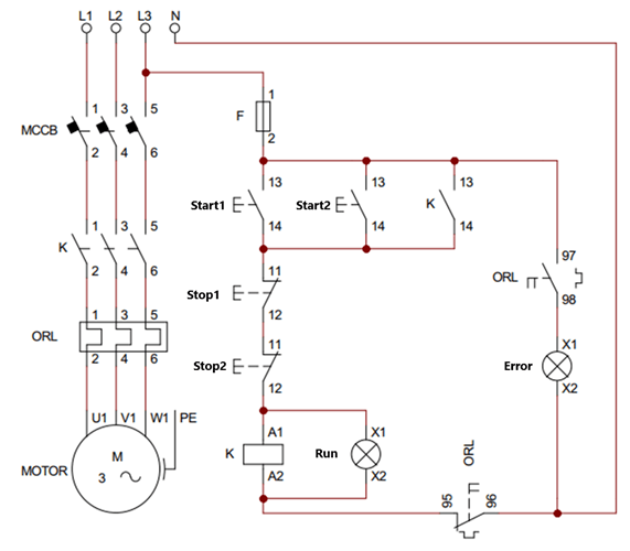
Circuits controlling a motor in two locations can place the controllers in two different places. The motor can control start and stop in both positions.
– Wiring diagram
+ Using two normally open push buttons: Start1, Start2 connected in parallel with each other and parallel to the auxiliary contact K.
+ Two normally closed buttons: Stop1, Stop2 connected in series.

Start stop contactor wiring diagram in 2 positions
– Working principle:
+ When we press Start1 or Start2, the control circuit is closed and the motor operates.
+ When we press the Stop1 or Stop2 button, the control circuit is open circuit, the motor stops working.
>>> See more:
What is a contactor – the most detailed article about contactor