In this post we will learn about what is diode? The most detailed information about diode: structure and symbol, operating principle, function, classification, characteristics.
Definition
A diode is a type of semiconductor device that only allows current to flow in one direction. It acts like a one-way valve, it has only two states: open or closed to allow or prevent the current from passing through it.
What is semiconductor diode?
– Specifications
+ Rated voltage: the maximum reverse voltage that the diode can withstand when reverse biased.
+ Rated current: When the diode works, losses will occur. The losses are mainly caused by the forward current. The power loss must not be allowed to heat the diode beyond the maximum temperature, otherwise the PN junction will be damaged. Therefore the diode is cooled and its current capacity is limited by the maximum value of forward current.
We can connect diodes in series or parallel when the voltage or current capacity of the it is not enough. Current capacity of diodes can be up to several thousand ampe.
+ Rate of change of current and voltage (di/dt, dv/dt)
When the diode changes from the closed state to the open state and vice versa. It needs some time to recover the charges and current back to the previous state.
The higher the operating frequency, the shorter the recovery time required. The rate of change of current and voltage must be less than the allowable value.
6 things to know about diode
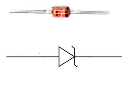
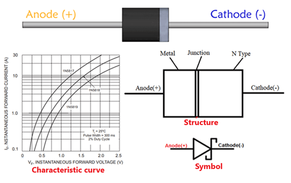
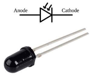
1. Structure and symbols
The diode is made up of a p-n junction.
+ In the p-side, the large number of holes is present. Hence, holes are the majority charge carriers in the p-type semiconductor. The holes carry most of the electric charge or electric current in the p-side.
+ In the n-side, the large number of free electrons is present. Hence, free electrons are the majority charge carriers in the n-side. The electrode connected to the n-side is the cathode (K).
The p-n layers in the diode structure are achieved by adding impurities into the Silicon (semiconductor).
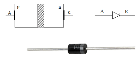
the structure and symbol
2. Working principle
When you apply an external power source across the diode. The p-side is connected to the positive pole of the source and the n-side is connected to the negative pole of the power source (forward bias). Charge carriers are formed and participate in the conductive process. The electric field force causes the hole from the p-side to move past the p-n junction into the n-side. And electrons move from the n-side to the p-side. So diode turns on.
In the case of reverse bias, the holes and electrons are pulled away from the junction and create an electromotive force inside the junction. This electromotive force acts to prevent the charge carriers from passing through the diode, so it turns off.
Refer to the video on the principle of operation of the diode – Lesics
3. V-A characteristic
The V-A curve consists of two branches:
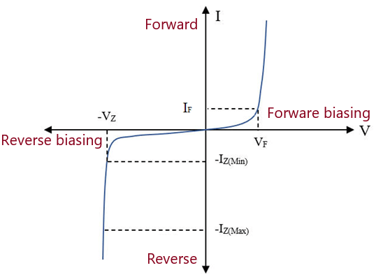
V-A characteristic
– Forward branch:
The diode will be forward biased so it allows current to pass.
– Reverse branch:
The diode is reverse biased, the reverse current through it has a very small value. When the reverse bias voltage is large enough to reach the breakdown voltage value, the voltage across the diode is reduced many times. The current value then depends mainly on the voltage and resistance of the circuit containing the diode in it. If the current increases too much, the diode will be damaged.
4. Dynamic properties
During the diode transition, when it changes from the conductive state to the off state, it is called the diode switching.
When the forward current through the diode turns off quickly, it will not follow the V-A characteristic.
+ After the forward current IF decreases to 0, the current through the diode does not turn off immediately, but it continues to conduct in the opposite direction.
+ After a short time, the reverse conductivity of the diode is lost and the current drops suddenly to the value of the reverse current (insignificantly small). At this point, the diode is able to withstand reverse voltage, its reverse resistance rZ is restored.
In the case of a diode connected in series with an inductive load (L). If the recovery current decreases too quickly, it will cause a back-voltage across the inductor L. This voltage combined with the switching voltage will cause a switching overvoltage. To avoid this, RC filters are used:
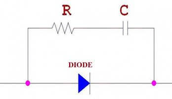
After the reverse resistance of the diode recovers, the RC circuit will slow down the process of turning off the current through the inductance L.
5. Application
+ Rectifier:
Converts AC voltage to DC voltage. The waveform after passing through the diode rectifier circuit is a direct current that will have ripples. To smooth the voltage, people combine with filter capacitors after rectification.
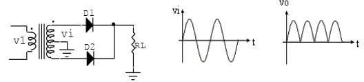
Rectifier circuit
+ Voltage shift circuit
The output AC signal will be shifted up or down with a DC voltage value compared to the input voltage signal. The waveform of the signal remains the same and the peak-to-peak value remains unchanged.
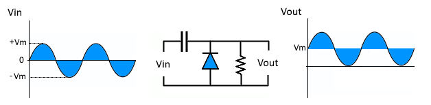
Voltage shift circuit
+ DC power reverse protection
With DC supply, reverse polarity protection circuit is necessary. The reverse connection of the power supply causes a large current through the circuit components. This may lead to damage to components.
Therefore, a protection diode is connected in series with the anode of the DC power supply. Assume that when we reverse the polarity of DC power supply, it will not allow the current through it.
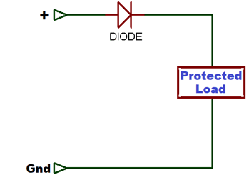
The reverse polarity protection circuit
+ Flyback diode
In inductive load control circuits, a sudden disconnection of the power supply generates a voltage that is opposite polarity and higher than the supply voltage. This voltage can cause damage to components in the circuit.
We can connect a diode in parallel, opposite to the load. When the switch switches closed to open, the inductor generates current through the diode. This consumes the energy generated on the inductor.
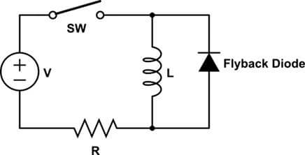
Flyback diode
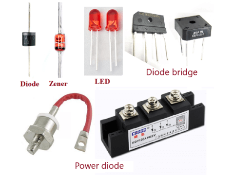
6. Special diodes
a. Zener
– What is zener diode?
Zener is a special diode that is doped with very high concentrations, Zener can operate in the breakdown region of the V-A characteristic.
What is Zener?
+ In the forward bias region, the Zener diode acts as a normal rectifier diode.
+ In the reverse bias region, when the reverse bias voltage reaches the UB voltage value, the current through the diode increases sharply, but the voltage across the Zener is constant. So it is used to stabilize the DC voltage.
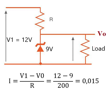
– Application of the Zener
As mentioned above, the application of the Zener is to stabilize the DC voltage.
Suppose we have a DC power source: V1 = 12V, but now we only need 9V to supply the load. We will use 9V Zener in series with the load to stabilize the voltage at the Vo output.
Then the selection of resistor R must satisfy that the current through the Zener diode does not exceed the rated current. Components usually have a capacity of 0.25W, with a voltage of 9V diode we can choose a resistor of R=200 Ohm.
b. What is Schottky Diode?
A Schottky diode is made of a metal-semiconductor junction. The n-type semiconductor acts as the cathode and the metal side acts as the anode of the diode.
What is Schottky Diode?
The Schottky diode has a very fast switching speed and the voltage across the diode when it is forward biased is low: 0.15 – 0.45V. This makes the Schottky less lossy, which is effectively used for sensitive application circuits.
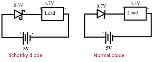
Low voltage drop
Cons: The Schottky diode’s ability to withstand reverse voltage is low: 50-100V. The reverse leakage current is higher than that of a conventional diode.
c. Light Emitting Diode (LED)
A device that converts electrical energy into light. It is doped with a high concentration of doped semiconductor crystal, which narrows the width of the diode band gap.
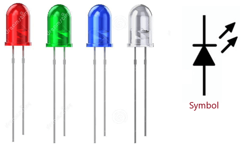
When the LED is forward biased, electrons move from a high energy level to a low energy level accompanied by photon emission. This phenomenon is called carrier recombination. LEDs can emit clear light depending on the threshold voltage. The voltage drop across the LED is usually higher than the rectifier diode.
d. Optical receiver diode
Optical receiver diode is a device that converts light into electricity. It has the same construction as a rectifier diode, but the outer shell of it is transparent glass to receive light hitting the p-n junction.
This type of diode also operate in reverse bias. When light hits the p-n junction, it provides energy for the valence electrons to be able to eject from the nucleus of an atom. This leads to the generation of electron-hole pair. The reverse current increases linearly with the intensity of light hitting the junction.
Optical receiver diodes are widely used in automatic control systems according to light intensity.
Reference articles
What is Schottky – Characteristics, Parameters and Applications