What is SCR? Structure, operating principle, characteristics of SCR. Learn about the two types of Thyristor control circuits
What is thyristor?
Thyristor or SCR (Silicon Controlled Rectifier) is a semiconductor device that acts as a control valve. Thyristors are widely used in electronic control boards.
A SCR will have 3 pins: anode, cathode and control pin G. It only allows conduction from Anode to Katot when a current is applied to control pin G.
Silicon Controlled Rectifier
5 things to know about SCR (Thyristor)
1. Structure and symbols
The structure of Thyristor consists of 3 layers of PN. Theoretically It has two types of structure: PNPN and NPNP, but in practice people only develop and use PNPN type.
The symbol of Thyristor is a semiconductor diode with additional control terminal G.
>>> See more: What is a diode – Detailed article about Diode
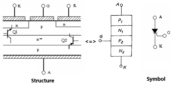
The structure and symbol of SCR
2. Working principle
We can see, Thyristor is two transistors PNP and NPN linked together through Base and Collector
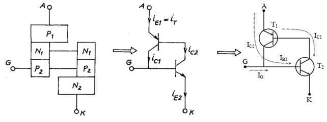
The principle of operation of SCR
When the control pulse is applied to pin G (or pin B of the NPN transistor), the NPN transistor will conduct. This current will flow from pin E through pin B of the PNP transistor and it will also conduct. The transistor will continue to conduct even if the control pulse at pin G turns off.
The current through pin C of the NPN transistor is the same as the current through the pin B of the PNP transistor and vice versa. Therefore the transistors will self-maintain conduction state.
Refer to the video below about the working principle of SCR
3. Characteristics
3.1 Thyristor states
When the thyristor is in the locked state, the anode can withstand a positive voltage relative to the cathode (UAK > 0). And when it is in the reverse state, the anode can withstand negative voltage compared to the cathode (UAK < 0)
– The process of thyristor switching from open state to conduction state satisfies two conditions:
+ When thyristor is in locked state (UAK > 0)
+ When the iG control current pulse is large enough.
– The SCR process changes from the conductive state to the open state (inverse state or locked state). This process consists of two stages:
+ Suppress forward current by changing the resistance or voltage between the anode and cathode.
Restore the locking function of the thyristor. After the forward current is suppressed, an interrupt time is required to switch the thyristor into the locked state.
3.2 V – A characteristic
The V – A characteristic is shown as shown below. Consists of 3 branches:
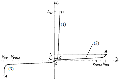
The V-A characteristic of the thyristor
– Forward branch (1): thyristor is in conductive state. The voltage drop between A-K is insignificantly small.
+ Unlike the diode, the forward branches of the thyristor do not start from zero but from iH (holding current in the conduction state). If the current value drops below iH, the thyristor returns to the locked state.
+ Immediately after closing the thyristor; Before the control pulse turns off, it is required that the forward current reach the latch current value iL (Latching). Hence iL > iH.
– Reverse branch (3): thyristor will be in reverse state.
+ Similar to diode, reverse current is very small. If the reverse bias voltage reaches the breakdown voltage (UBR), the current through the thyristor increases dramatically. Then the thyristor junction is damaged.
When the thyristor is in the reverse state, the input of a control pulse to the SCR will futilely increase the reverse current.
– Lock branch (2): Thyristor is in locked state.
+ If there is no control pulse, the locked branch is similar to the reverse branch. Similarly, we have the closing voltage uBO instead of the breakdown voltage uBR. When the voltage reaches the uBO value, the thyristor switches from the locked state to the conductive state.
+ When the current at the G pin of the SCR (iG) changes value. Depending on its magnitude, the value of the locking voltage also changes (the lockout voltage will decrease as iG increases).
4. Dynamic properties
When we apply a locking voltage to the thyristor, the semiconductor layer acts like a capacitor, its capacitance depends on the magnitude of the applied voltage.
4.1 Switching closed
The closing of the Thyristor does not occur as soon as a control pulse (iG) is applied to the gate. The charge passing through the semiconductor layer will gradually increase and the locking voltage on the thyristor will decrease. Normally, the closing time of the thyristor is: 3 – 10us.
When the conductive current increases too quickly, only one part of the cross-section leads to overload. This can cause the temperature to rise excessively, damaging the component.
4.2 Open Switching
In the first stage, turning off the thyristor is similar to turning off the diode.
After recovering the reverse resistance, the Thyristor still needs more time to recover the locking ability.
The minimum time (tmin) to turn off the SCR starts from when the forward current reaches zero, until the lock voltage is present again (and IG = 0) but it cannot make the SCR conduct. If the lock voltage is applied earlier than the time tmin, the SCR may conduct even though no control pulse has been applied to the gate terminal.
The time it takes for the SCR to turn off depends on conditions such as: semiconductor temperature, current, rate of drop-off, and reverse voltage. Thyristors typically have tmins in the range of a few us to hundreds of us.
5. Load capacity
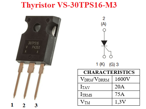
The thyristor’s ability to withstand voltage and current and overload is considered similar to that of a diode. Repetitive peak Reverse voltage VRRM and Repetitive peak off-state voltage VDRM are usually equal, to indicate the maximum allowable voltage values applied to the thyristor.
The voltage capacity of the thyristor is normally in the range of 5-7 kV. The average current reaches about 5000A. The voltage drop when conducting is in the range of 1.5 – 3V. Most thyristors are air-cooled.
The following table shows the typical parameters of the thyrsistor VS-30TPS16-M3
|
Parameter |
Value |
Explanation |
|
VRRM |
1600V |
Repetitive peak Reverse voltage |
|
VDRM |
1600V |
Repetitive peak off-state voltage |
|
VRSM |
1700V |
Non-repetitive peak reverse voltage |
|
dv/dt |
500V/us |
Maximum rate of rise of off-state voltage |
|
IRMS |
30A |
RMS – On state current |
|
ITAV |
20A |
Mean on state current |
|
di/dt |
150A/us |
Maximum rate of rise of turned-on current |
|
VT |
1,3V |
Direct on state voltage |
|
VGT |
2V |
Gate trigger voltage |
|
IGT |
45mA |
Gate trigger current |
|
IH |
150mA |
Holding current |
|
IL |
200mA |
Latching current |
6. Control circuit
In power converters using SCR, the power and control circuits need to be insulated. Similar to the driver circuit for transistors, mosfet. We can use pulse transformer or isolating optocoupler.
6.1 Control circuit using pulse transformer
In order for the thyristor to conduct, the current applied to its G pin must be large enough at the beginning. Because the inverse layer is not good, it is not allowed to appear on it even a very small negative voltage (UGK < 0). The circuit below uses two diodes D1 and D2 to prevent reverse current, ensuring voltage UGK > 0.
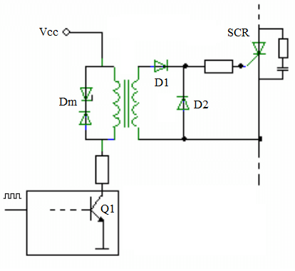
Thyristor driver circuit using pulse transformer
When a high signal is applied to pin B of transistor Q1, Q1 conducts and it acts as a closed switch. At this time, the source voltage is applied to the primary winding of the pulse transformer, so an induced voltage appears in the secondary winding. This induced voltage is applied to the G pin of the thyristor, so the thyristor conducts.
When the input signal is low, transistor Q1 does not conduct, so the transformer primary coil is not energized. When the coil is disconnected, it generates current through the diode Dm. The purpose of using diode Dm to quickly turn off the magnetizing current when the pulse is interrupted. If the diode Dm is not used, the magnetic current continuously increases after each pulse is applied.
If we use shock with ON time is long will increase the loss. Therefore, we will use a control signal in the form of a pulse train.
Thyristor protection circuit: Use an RC circuit in parallel with the SCR to protect against overvoltage. The circuit can be combined with a protective reactor in series with the SCR against a rapid increase in current through the device.
6.2 Control circuit using optocoupler
Opto used in the control circuit can be Transistor opto-isolator or Opto-isolated SCR.
The input signal is applied to the LED of the optocoupler, the LED glows and transmits the signal to the thyristor of the optocoupler. Then the thyristor of the optocoupler conducts and the thyristor of the external circuit also conducts.
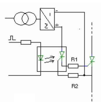
Control circuit using optocoupler
The opto circuit requires a separate DC power supply, thus increasing the cost and size of the control circuit.
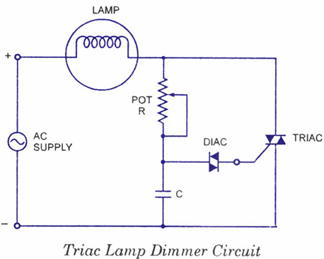
In many applications, a simple driver circuit uses the DIAC as shown below. The magnitude of the excitation angle depends on the charging time for the capacitor (determined by the time constant RC) and the applied voltage of the diac. The advantage is that the control circuit uses the power supply from the power circuit. The excitation angle control range is limited.
>>> Related Articles
8 schematic diagrams of 3 phase rectifier circuit