Two schematic diagram of full wave rectifier circuit with capacitor filter, why use capacitor filter in rectifier circuit.
Full wave rectifier circuit with capacitor filter
The output of the full-wave rectifier circuit is a DC voltage, the voltage value varies from 0V – Vmax. This voltage cannot be used to power ICs, microcontrollers or sensors. To generate pure DC voltage, capacitors filter are often used in parallel with the output load.
1. Bridge rectifier circuit with filter capacitor
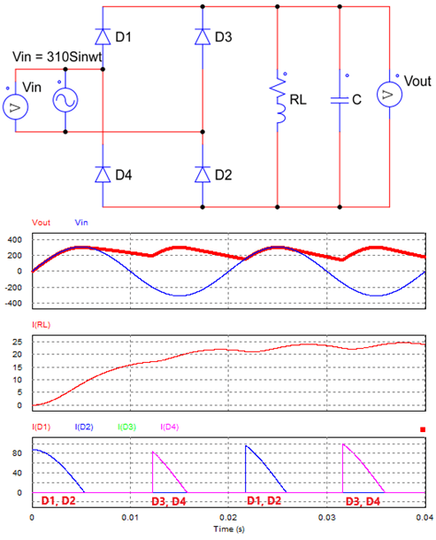
Bridge rectifier circuit with filter capacitor
The principle of the bridge rectifier circuit using capacitor filter is very simple. When the source voltage is greater than the voltage across the capacitor, the diode will be forward biased, the capacitor is charged. Conversely, when the source voltage is less than the voltage across the capacitor, the diodes are reverse biased. The capacitor will begin to discharge through the load.
We see that the capacitor voltage when discharging does not drop suddenly. Therefore, the output voltage has less ripple than the circuit without capacitor filter. The output current still increases whether the capacitor is charged or discharged.
2. Center tapped rectifier circuit
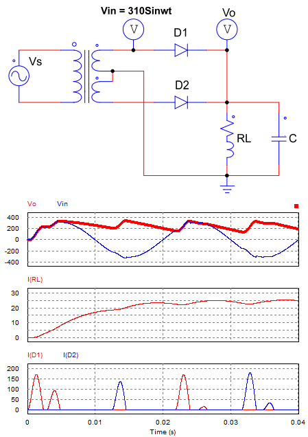
Center tapped rectifier circuit
Current through the diode: ID = IRL + IC, the charging current of the capacitor has a larger value than the current passing through the load. Therefore, it is necessary to choose a diode with a rated current large enough to charge the capacitor.
Advantages
The figure below is the output waveform of a full wave rectifier circuit with capacitor filter and without using capacitor filter.
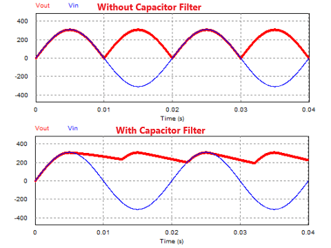
Full wave rectifier with and without filter
Some advantages of rectifier circuit using capacitor filter:
+ Less ripple, depending on the value of the capacitor, the output waveform has more or less ripple.
+ Higher average output voltage and current value.
+ When the value of the capacitor is large enough, the output voltage waveform is a straight line. And this circuit is often used in power supply circuits.
>>> Related posts:
Half wave rectifier circuit diagram (8 circuits)
Single phase full wave Rectifier (6 circuits)
Three phase bridge rectifier diagram (5 circuits)
8 schematic diagrams of 3 phase rectifier circuit