Learn about the working principle of 3 phase controlled half-wave rectifier circuit (2 circuit diagrams). How to generate pulses to fire thyristors in a controlled rectifier circuit.
Working principle of the control circuit
A three-phase half-wave controlled rectifier is a circuit that uses three thyristors (or SCRs) to convert AC voltage to DC voltage. Only one SCR can conduct at a time.
For example, when V1 is maximum, SCR1 is forward biased; SCR2, SCR3 is reverse biased. So if SCR1 is fired, then SCR1 will conduct, and SCR2, SCR3 turn off. Similarly for SCR2 and SCR3, voltage V2 and V3 should respectively be greater than other two phase voltages.
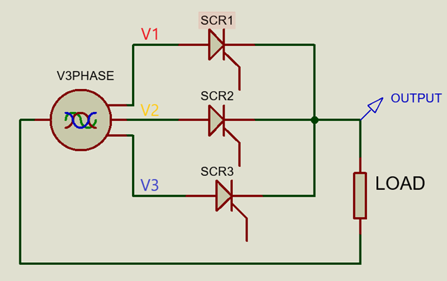
3 phase half wave controlled rectifier
The input phase voltages V1, V2, and V3 have the same amplitude and frequency with 120◦ phase shifts. The control signal must be synchronized with the input phase voltage. In Psim software, we design a control circuit that generates control pulses.
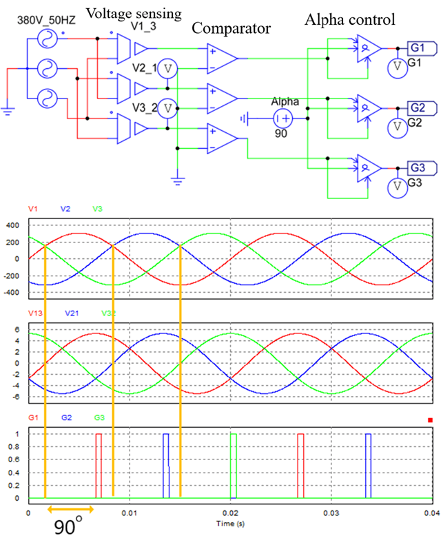
Control circuit designed on Psim software
The control circuit uses a voltage sensing block to convert the input phase voltage to a smaller voltage that can be measured. And move the electrical zero degree angle of the control pulse to a new position where the thyristor can conduct immediately when the thyristor is fired.
After that, this signal will pass through a comparator block to generate a digital signal. This digital signal puts into Block Angle Control. When the signal level is high, the alpha block will wait for a time t (t = alpha) and then output a signal to activate the thyristor.
3 phase half wave controlled rectifier (2 circuits)
1. Controlled rectifier with resistive load
The 3 phase controlled rectifier uses 3 SCRs instead of diodes. The circuit below uses a load of resistor R = 50 Ohm and an alpha trigger angle of 90.
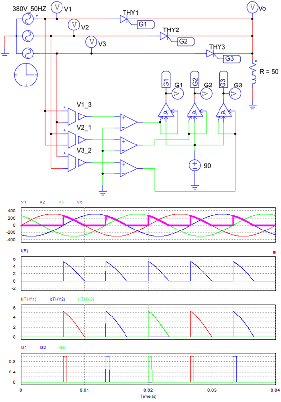
Three phase half wave controlled rectifier with R load
Working principle:
+ When the phase voltage V1 is maximum, Thy1 is forward biased. If there is a control pulse G1 placed on the gate terminal of Thy1, then Thy1 will conduct, so output voltage Vo = V1.
Unlike the uncontrollable rectifier circuit, when V2 > V1, Thy1 will continue to conduct (Vo = V1). Because when the phase voltage V2 is the largest, the control pulse G2 is not available, so Thy2 is still OFF; Thy1 continues to conduct.
Until V1 < 0, Thy1 is reverse biased, so it stops conducting (Vo = 0, Io = 0).
+ When there is a control pulse G2 put into the gate terminal of Thy2, Thyristor 2 will conduct. The principle of operation is the same for Thyristor3.
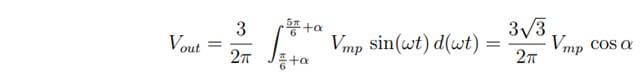
=> Output voltage waveform is identical to the input phase voltage corresponding to the thyristor conducting at the time. Vout is discontinuous for a resistive load. The average value of output voltage: (Vmp = √ 2. VRMS)
2. Three phase half wave controlled rectifier with RL load
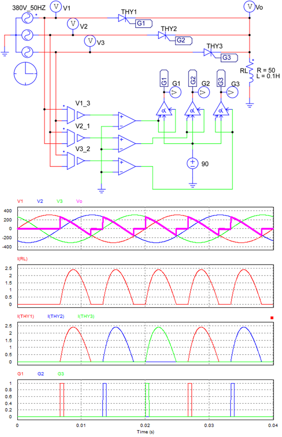
Three phase controlled rectifier with RL load
– Working principle:
+ When V1 > V2 > V3: If there is a control pulse G1, thyristor1 will conduct (Vo = V1 > 0).
+ When V1 < 0: Thy1 is reverse biased, but it continues to conduct. Since the load RL generates energy, the current flows in the same direction as the previous current, which causes thy1 to continue in the conduction state. The output voltage is equal to the source voltage, so it has a negative value Vo = V1 < 0, Io > 0.
+ When the load runs out of energy, thy1 stops conducting (Io = 0, Vo = 0). The output current is interrupted. If L has a sufficiently large value or the excitation angle is small, the output current can be continuous.
The disadvantage of a 3 phase half wave controlled rectifier with an RL load is that the output voltage has parts less than zero (Vo < 0).
+ The principle of operation is similar for thy1 and thy2.
>>> Related posts:
Half wave rectifier using scr and diode (8 circuits)
3 phase bridge rectifier circuit (4 circuits)
3 phase half wave rectifier circuit (4 circuits)
>>> See also: Half wave controlled rectifier working & waveforms – Engineering Funda