Three phase half wave uncontrolled rectifier circuit is a circuit used to convert 3 phase AC voltage into DC voltage using three diodes. This rectifier circuit is widely used because the output voltage has a good waveform and a large voltage value. These circuits are essential components in modern equipment: inverters, welding machines, etc.
Three phase half wave uncontrolled rectifier (4 circuits)
The 3 phase half wave rectifier circuit uses three diodes, the 3 phase power supply requires a neutral wire. The anode of each diode is connected to one phase of the power supply. The cathode of the 3 diodes are connected together and connected to the load.
In this circuit, people have proven that only one diode can conduct at a time. And it is the diode connected to the AC voltage source whose instantaneous voltage value is the largest.
1. Rectifier circuit with R load
Schematic diagram of half wave rectifier circuit with resistive load and output waveform of current and voltage is drawn as shown below:
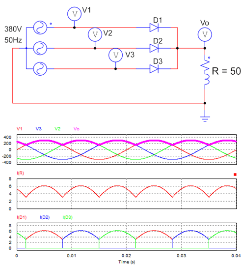
Three phase half wave uncontrolled rectifier with R load
Working principle:
+ From 0 – 30 electrical degrees: V3 (voltage of phase 3) is the largest, so diode D3 will be forward biased. During this time, diodes D2 and D3 are reverse biased. Current through D3, load and to neutral. As a result, the current will go from phase 3 to D3, R to neutral.
+ From 30 – 150 electrical degrees: V1 is the largest, so D1 starts conducting; D2 and D3 remain off.
+ Similarly, after 120 electrical degrees, D2 conduct; D1 and D3 turns off.
=> During one cycle of the supply voltage (T = 0.02s), each diode conducts for a period of T/3. The load current is the current of each diode while this diode is conducting. The output current of this circuit is continuous.
– Average output voltage
+ The output voltage is a variable DC voltage. The period of the output waveform is T/3.
+ Each diode conducts for a period of T/3, so the average voltage value on each diode is: ID = Io/3.
>>> See also: 3 phase half wave rectifier (3D Animation)
2. 3 phase half wave rectifier with RL load
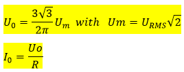
Half wave uncontrolled rectifier circuit with RL load
– Working principle:
+ The output voltage waveform does not change compared to the R load rectifier circuit. Each diode will conduct in 1/3 of the cycle T.
+ The output current waveform has a smaller ripple than the circuit above. Because when we use RL load, the current passing through the load does not change suddenly. The current lags behind the voltage. As each diode switches, the current continues to increase until steady state is reached.
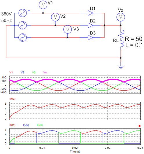
3. Rectifier circuit with filter capacitor
To smooth the output voltage: people use a filter capacitor with a large enough value in parallel with the load. The voltage across the RL load is equal to the voltage across the capacitor: VRL = VC. In the first cycle, the supply voltage increases, and the capacitor will charge. The voltage across the capacitor increases to the maximum voltage.
+ If the voltage on the capacitor is less than the supply voltage, the capacitor will be charged through the diode. We observe that the current of the diode (ID) value is larger than the current of RL load (IRL). Because the current to charge the capacitor is large (ID = IRL + IC.)
+ If the capacitor is large enough, the output voltage and current will be set as a straight line.
Output waveform when using filter capacitor
4. Three phase half wave rectifier with RLE load
Three phase rectifier circuit with RLE load: R = 10, L = 0.1H, E = 250V.
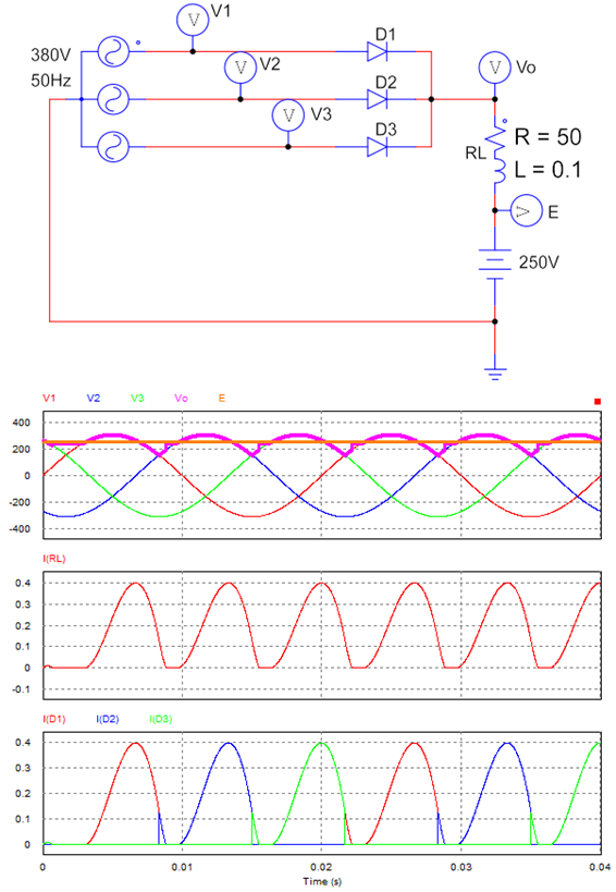
Three phase half wave uncontrolled rectifier with RLE load
– Working principle:
+ When V1 > E, diode D1 will turn on (Vo = V1).
+ When V1 < E, D1 is reverse biased; the diode will turn off. But at this point, the load will emit current through D1, causing D1 to continue conducting (Vo = V1 < E).
+ When V1 < V2 < E, D2 will conduct and D1 turns off (Vo = V2 < E).
+ When the load has run out of energy and V2 < E, D2 will turn off (Io = 0 and Vo = E).
+ Until V2 > E, D2 will conduct.
=> In this circuit, we can see that the current through the load is interrupted.
What is the difference between rectifier and bridge rectifier
There are many types of 3-phase rectifier circuits such as half-wave, full-wave, uncontrollable, and controlled rectifier circuits.
>>> See Also: Three phase bridge rectifier diagram (5 circuits)
+ The output waveform of a 3-phase bridge rectifier is a smaller ripple than a half-wave rectifier. Assume that T is the period of the supply voltage. Then the period of the bridge rectifier circuit is T/6, and the period of half-wave rectifier is T/3.
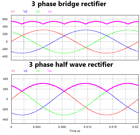
Waveform of three phase rectifier circuit in one cycle
+ Average output voltage of a bridge rectifier is twice as high as a half-wave rectifier. If we use a filter capacitor, then the bridge rectifier will require a smaller filter capacitor value than a half-wave rectifier.
+ The half-wave rectifier circuit requires the supply voltage to have a neutral wire (N). The bridge circuit does not require a neutral wire.
+ Bridge rectifier circuit costs more. For the controlled bridge rectifier circuit, the control pulse generator circuit 6 SCR will be very complicated and expensive.
>>> Related posts:
Half wave rectifier circuit diagram (8 circuits)