In this article, we will learn about three phase full wave uncontrolled rectifier circuit (4 circuits): Define, structure and principle of each 3-phase rectifier circuit.
What is three phase full wave rectifier?
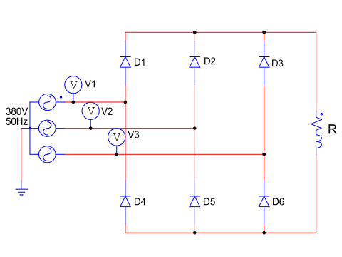
Three phase full wave uncontrolled rectifier circuit is a circuit that converts three phase AC voltage into DC voltage. The bridge rectifier circuit uses six diodes. Each phase of the power supply is connected to a pair of diodes shown in the figure below.
What is 3 phase full wave rectifier?
Three phase full wave rectifier are of great significance in the field of power electronics. Since this circuit produces an output voltage with a low ripple, the average output voltage is high. The frequency of the output voltage waveform is six times the input voltage frequency; this means less capacitive filtering and a much smoother output voltage.
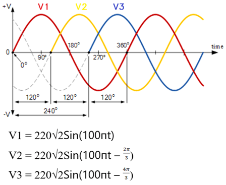
Assuming that: we will use an ideal 3-phase power supply. Power supply 3 phase with amplitude 380V, frequency is 50Hz. Each power supply phase will be out of phase by 120 degrees of electricity. The voltage equation of each phase V1, V2, V3 is as follows:
>>>See also: Working principle of 4 circuits of three phase half wave rectifier
3 phase full wave rectifier circuit (4 circuit diagrams)
1. Rectifier circuit with R load
Three-phase full wave rectifier circuit will use six diodes. Each power phase will connect to the midpoint of a pair of diodes. The cathode of the three top diodes is linked together, creating a positive (+) terminal for the load. And the anode of the three bottom diodes is connected as the negative (-) terminal for R load.
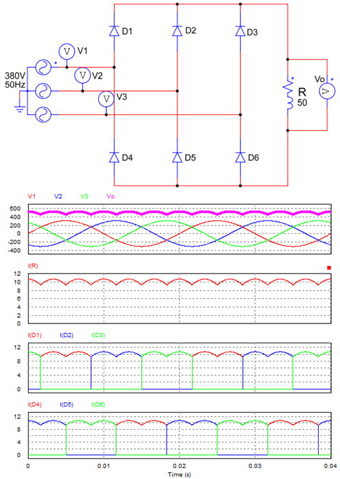
3 phase full wave rectifier circuit with resistive load
– We observe that:
+ If T = 0.02s is the period of the source voltage, we see that the period of the output waveform will be T/6. The output voltage will be the line voltage (line-line).
Compared with the three phase half wave rectifier circuit, the output voltage cycle is T/3. The 3 phase full wave rectifier circuit has a better output voltage waveform, reducing the filter capacitor value.
+ Each diode will alternately conduct for about 1/3 cycle. The diode above will conduct when the voltage at its anode is the largest compared to the other two diodes. Similarly, the diode below will conduct when the voltage at its cathode is the smallest compared to the other two diodes.
We observe that: the output current is continuous. The diodes will conduct in the order of six steps: D1+D5, D1+D6, D2+D6, D2+D4, D3+D4, D3+D5. Each pair of diodes will conduct for only 600 of a cycle (T/6) at any one time.
– Working principle:
+ At the beginning of the cycle, V3 (the voltage of phase 3 ) is the largest, so D3 conducts, while Diode D1 and D2 reverse bias. At the same time, V2 is the smallest, so D5 conduct, while D3 and D6 are reverse biased.
=> Current will start from phase 3 through D3, R, D5 and return to phase 2. The voltage across the load will be Vo = V3 – V2.
+ At 30 electrical degree, the value of V1 is the largest, so D1 conducts. V2 is the smallest, so D5 continues to conduct.
+ 60 electrical degrees later, V1 is the largest, and V3 is the smallest, so diode D1 and D6 conduct.
+ 60 electrical degrees later, V2 is the largest, and V3 is the smallest, so diode D2 and D6 will conduct. The principle of operation is the same for the other half of the cycle.
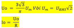
– Formula for calculating average output voltage
The average output voltage and current are given by the formula:
Refer to the animated video “How does a three-phase full wave rectifier work“
2. Rectifier circuit with RL load
For the rectifier circuit using an inductive load. We assume L = 0.1 H, R = 50 Ohm. We simulate the rectifier circuit on Psim software and get the following waveform:
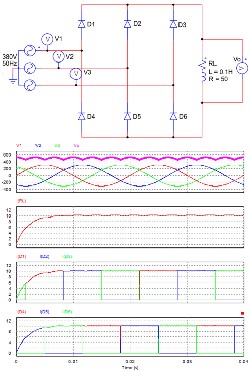
Three phase full wave rectifier circuit with RL load
– Principle of operation
The output waveform of the voltage and the conduction order of the diodes is the same as that of the rectifier circuit using a resistive load.
+ The current output is small fluctuation because the characteristics of the inductor do not allow the current through it to change suddenly. Therefore, the ripple of 3 phase bridge rectifier circuit using load RL is small.
3. Rectifier circuit with RLE Load
Rectifier circuit with load components including: R = 50, L = 0.1 and E = 250; circuit diagram as follows:
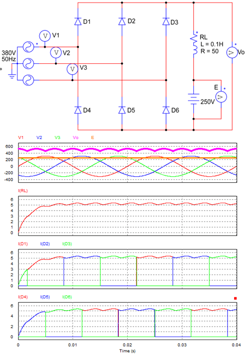
Three phase full wave rectifier circuit with load RLE
– Working principle:
+ The voltage on the load is the line voltage between the two phases of the source. When the line voltage is greater than E, the waveform of the rectifier circuit with RLE load is not different from the load RL.
+ The current through the load is continuous, and the output current has a small fluctuation. The average current of the rectifier circuit with RLE load is smaller the rectifier circuit using RL load (Io = Vo/R). The average value of output current: Io = (Vo – E)/R
4. 3 phase rectifier circuit using filter capacitor
We all know, the output voltage waveform of the 3 phase rectifier bridge circuit is not a standard DC voltage. To smooth the output waveform, we will connect the capacitor parallel with the load. The circuit diagram and waveform are drawn as shown below.
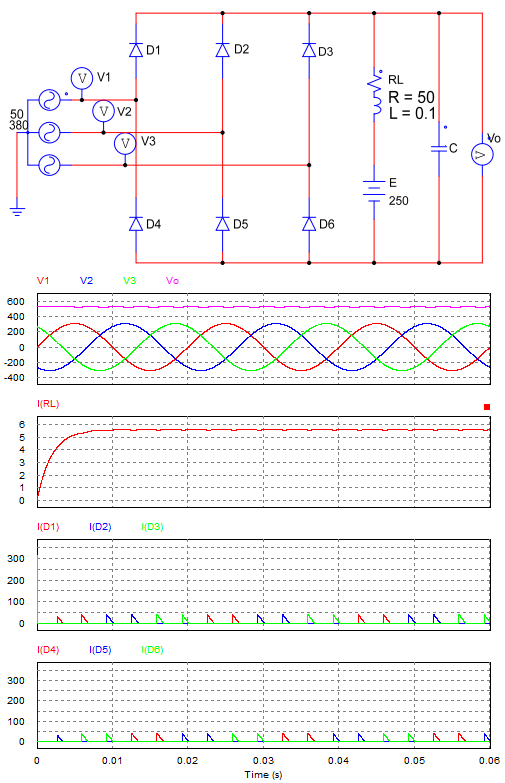
Three phase full wave rectifier circuit using filter capacitor
– Working principle:
+ In the first cycle, diode D3 and D5 will conduct. In a short period of time we see that the current on D3 and D5 is large. Due to the current passing through the load and at the same time charging the capacitor. The capacitor is charged until the voltage across it is equal to the peak value of the line voltage (Vd = V3 – V5).
+ When the line voltage decrease, the capacitor discharges through the load. If the voltage across the capacitor drops below the line voltage, diodes are forward biased. And once again, the capacitor is charged.
+ Due to the 3-phase bridge rectifier circuit, the output voltage has a small ripple. So we will choose a capacitor with a lower value than a 3-phase half-wave rectifier circuit and a 1-phase bridge circuit. The calculation to select the capacitor value is very complicated, so we will conduct simulations to choose the capacitor value.
=> The output voltage waveform of the rectifier circuit using a capacitor is the standard DC voltage.