The bridge rectifier output voltage is a time-varying DC voltage. This article will learn about the output waveform characteristics and the formula for calculating the output voltage and current value of the diode bridge circuit.
Bridge rectifier output voltage waveform
1. Circuit diagram
Circuit diagram of bridge rectifier with resistive load is shown below. Figure a is a bridge rectifier circuit without a transformer. Figure b is a bridge rectifier circuit using a transformer, usually a transformer used to reduce the value of AC voltage.
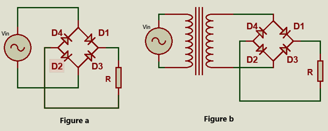
Circuit diagram of bridge rectifier
The output current and voltage waveform of the bridge rectifier circuit, corresponding to the input voltage Vin applied to the bridge rectifier as shown below. The input voltage has a frequency of 50 Hz or a period of: T = 0.02s.
2. Operating principle:
In the range of 0 < t < 0.01, the supply voltage Vin > 0. Therefore, D1 and D2 will conduct, and D3 and D4 are reverse biased.
After half-cycle 0.01 < t < 0.02 the source voltage changes polarity. Hence D3 and D4 will conduct, and D1 and D2 are reverse biased.
We see that after every half cycle (T/2 = 0.01), the output waveform is repeated. In other words, the output frequency is twice the input frequency.
3. Output waveform
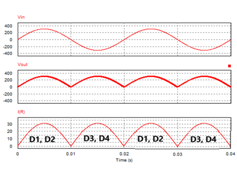
Output voltage and current waveform
We can see that in each cycle there are two pairs of diodes that conduct alternately. When the input current changes direction from positive to negative, the output current is still positive. In the case of using a resistive load, the output current waveform is the same as the output voltage waveform.
Formula for calculating output voltage and current
Input voltage equation: Vin = Um.Sin(wt)
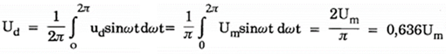
+ Average output voltage value: Ud
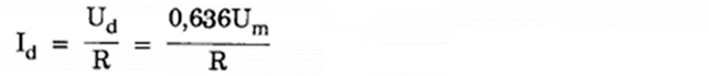
+ Average output current value: Id
+ RMS output voltage: URMS
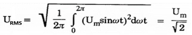
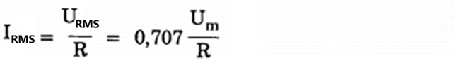
+ RMS output current: IRMS
For a bridge rectifier circuit using filter capacitors, the ripple will be smaller and the average voltage will increase (Figure below). If the value of the capacitor is large enough, the output voltage will be a straight line. And then the average output voltage is equal to the peak voltage of the source Ud = Um.
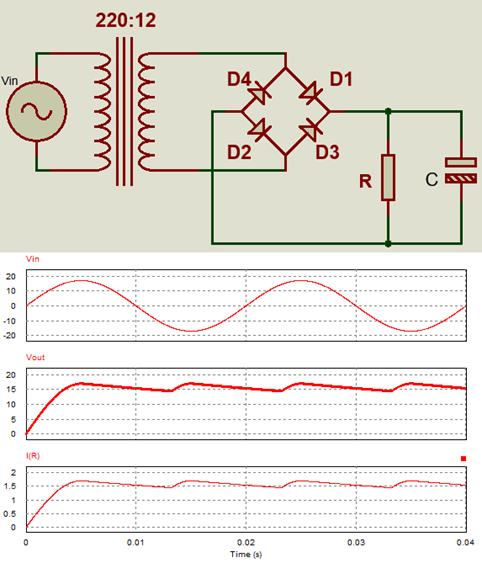
Bridge rectifier circuit with filter capacitor
>>> See more:
Working of single phase bridge rectifier (10 circuits)
Half wave rectifier circuit diagram (8 circuits)
Center tapped full wave rectifier (7 circuits)
8 schematic diagrams of 3 phase rectifier circuit