Learn about the output waveform characteristics of a full-wave circuit using two diodes. What are the disadvantages of center tapped full wave rectifier ?
Output characteristics of full-wave rectifier
– Wiring diagram:
The figure below shows the circuit diagram and output waveform of a full wave rectifier using two diodes.
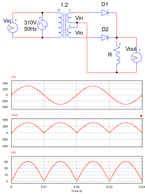
Diagram and waveform of a full-wave rectifier circuit
This circuit consists of a transformer whose secondary has a center point, 2 diodes and R load. The input AC power is connected to the primary of the transformer. In the secondary of the transformer connected with two diodes as shown in the figure. The midpoint of the transformer connected to the load R.
– Working principle:
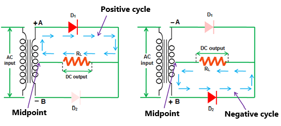
+ In the positive half, diode D1 conducts, current passes through D1 to the load. If we ignore the voltage drop on the diode, then the load will be parallel to the source, so the output voltage is equal to the input voltage.
+ In the positive cycle, diodes D2 conduct, current flows from the source through D2, through R and back to the source. At this time, the power supply is parallel to the load, but in the opposite direction. Therefore, the output voltage has the same magnitude as the input voltage but opposite sign. Looking at the figure, we can see that in the positive cycle, the output voltage is symmetrical with the input voltage across the 0V line.
==> The voltage is rectified in both cycles, the output frequency will be 2 times the input frequency.
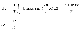
– Output average voltage and current:
4 disadvantages of center tapped full wave rectifier
1. The cost of the circuit
This circuit requires the use of a transformer, so it will make the circuit more expensive than a bridge rectifier which has the same output waveform.
2. The size of Circuit
The center tapped full wave rectifier circuit will take up more space since the size of the transformer is much larger than that of the diodes. Especially with large capacity circuits, the larger the transformer size.
3. Load capacity
Compared with the bridge rectifier circuit, the center tapped full wave rectifier is less used in high power applications. Since the transformer will carry the output load directly, the rated current of the transformer is limited. Therefore, the circuit is not suitable for applications with high voltage and large current loads.
4. Reverse voltage of diode
During the half cycle, when one diode conducts the other diode will be reverse biased. With the reverse voltage applied to it equal to 2 times the source voltage (2*Vin). Therefore, the choice of diodes should consider the reverse voltage rating of the diodes. If we choose diode with reverse voltage smaller than the actual voltage value will lead to diode breakdown.
>>>> Related posts
Center tapped full wave rectifier (7 circuits)
8 schematic diagrams of 3 phase rectifier circuit
Working of single phase bridge rectifier (10 circuits)