If you’re looking to understand DOL starter control circuit, you’re in the right place. Induction motors require a significant starting torque during their start-up, resulting in a high initial current. This high current, if repeated every day, can damage the motor windings. For larger motors, starting them directly can also cause a voltage drop on the grid. Therefore, the direct starting method is only suitable for motors with a capacity of less than 5 horsepower.
What is dol starter control circuit
A DOL Starter control is a circuit used to start a three-phase AC motor by supplying power directly to the motor’s stator coil. The circuit typically consists of simple devices like a contactor, thermal relay, and circuit braker. The primary contactor is usually operated using a push button or switch.
There are multiple ways to start an electric motor, including star-delta starting, using a soft starter, using an inverter, and using a stator series resistor. However, for motors with high power and an operating capacity of less than 10hp, the direct starting method is still widely used. The direct start method has its own set of advantages and disadvantages, which must be taken into consideration before selecting it as a starting method.
* Advantage:
+ A simple electrical circuit, low-cost
+ Overcurrent and short circuit protection functions.
* Disadvantages:
+ High starting amps
+ Acceleration time cannot be adjusted. Some machines have ramp-up time requirements because starting up too quickly can cause mechanical damage.
Some three-phase motor starter circuits
1. DOL starter control circuit with circuit breaker
This circuit is a basic DOL starter circuit that consists of only one device, which is a manually controlled MCB. It can only be used for motors with small capacity and does not have any overload protection function. However, one of the major drawbacks of direct starting with MCB is that it is not safe for the operator. If electrical safety rules are not applied, the operator might receive an electric shock.
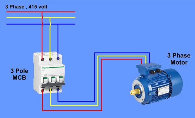
Direct motor starting circuit
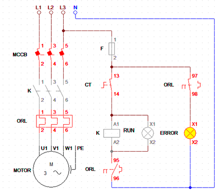
2. Motor starting circuit using contactor – 1
The circuit operates the three-phase motor by controlling the closing and disconnecting of contactor K. In the power circuit, the three motor phases connect to the main contact of the contactor through the thermal relay (ORL). In the control circuit, the switch connects to the contactor coil and the normally closed contact of the thermal relay.
+ When the switch CT is closed, it activates the contactor coil. The contactor coil is powered and changes the contactor state from open to closed. This allows the three-phase voltage from the power supply to be applied to the motor’s three phases, causing the motor to start.
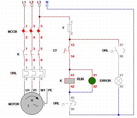
+ When the switch CT is flipped to the open state, the coil contactor K loses power. The spring force within the contactor pushes its contacts into the open state, which stops the flow of current into the motor. Consequently, the motor starts to come to stop freely.
3. Motor starting circuit using contactor – 2
This circuit uses two push buttons to control the contactor, which is an improvement over the switch-based control circuit. Although the push-button circuit for direct motor start is more complex, it offers the advantage of automatically returning to its original state after we stop using it. As a result, this circuit using push buttons ensures safety for both equipment and people during power outages.
The ON push button’s contact is usually open, while the OFF push button’s contact is normally closed. When we stop pressing the button, it returns to its old state. To keep the K coil energized, people use a K contact in parallel with the ON button.
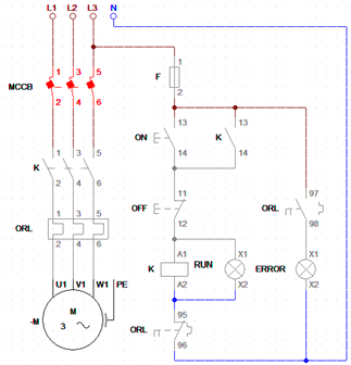
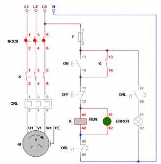
Dol stater control circuit using contactor
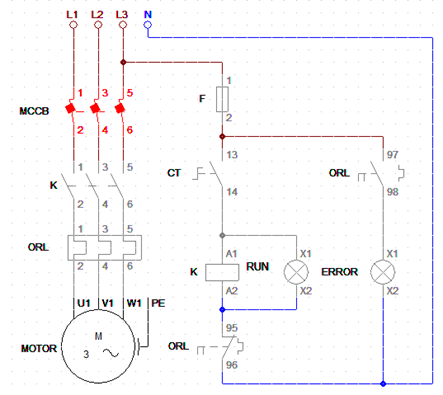
In the two circuits shown above, the motor may become overloaded for a prolonged period of time. In such cases, the bimetal bar inside the thermal relay will heat up. When the temperature of the bimetallic bar reaches a certain point, the contact states of the thermal relay will change. This will cause the Error indicator light to turn on, and the motor will stop working simultaneously.
The Error light lights up to warn that the motor is overloaded
4. Motor starting and reversing circuit
The three-phase motor direct starting circuit can also be used for motor reversing. To reverse the direction of the motor, we simply need to swap the positions of two of the three power wires that supply the motor.
In the image presented below, we can observe the contrast between closing contactor KF and contactor KR. When KF is closed, the first phase and third phase are interchanged before entering the motor, effectively reversing the direction of a three-phase motor in a safe and straightforward manner
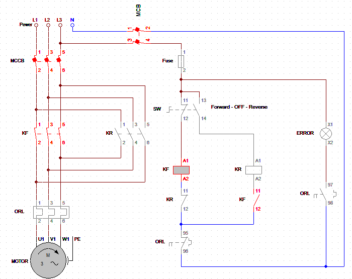
The motor rotates in the forward direction
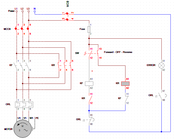
The motor rotates in the reverse direction
Conclusion
Hopefully, the four examples I presented will help you understand the principle of direct starting circuits and apply them in practice.
>>> Related articles:
4 Star Delta Starter control circuits
3 Sequential motor control circuits
Full wave bridge rectifier (4 circuit diagrams)
>>> Video tham khảo