Can a 3 phase motor run with single-phase voltage? In today’s article, we present two ways to run a three-phase motor on a single-phase power source.
Why do we use three-phase motors?
Like any other type of electrical motor induction motor, a 3 phase induction motor is constructed from two main parts, namely the rotor and stator. Stator is a stationary part of induction motor. A winding stator is placed in the stator of induction motor and the three phase supply is given to it. Three-phase motors operate smoothly and have higher efficiency than single-phase motors.
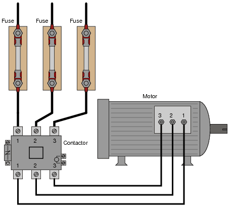
Power supply to three-phase induction motor
Therefore, three-phase motors are very widely used motors in industry and commerce. However, not every place has three-phase electricity. In some places where we only have single-phase power, using a 380V 3-phase motor is a bit difficult.
There are several ways to run a three-phase induction motor with single-phase power, each with its own advantages and disadvantages. Let’s find out together!
Can a 3 phase motor run with single-phase voltage?
1. Using capacitor
When applying single-phase power to a three-phase motor, the motor cannot create a rotating magnetic field, so the motor cannot operate. At this time, if we use our hands to rotate the motor shaft, the motor will operate normally.
Based on that principle, people use capacitors to start three-phase motors. The capacitor causes the magnetic flux produced on the motor coils to deviate by 90 degrees, thereby creating a rotating magnetic field.
For example, a three-phase motor with the symbol: Delta 380V/ Star 220V will have the following wiring diagram.
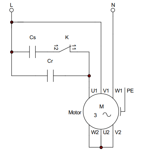
Start three-phase motor with capacitor
Working principle
The motor connection diagram is drawn as shown above. When power is applied to the motor, the starting capacitor is connected to the circuit. When the motor operating speed is close to the rated speed, contact K will open and disconnect capacitor Cs from this circuit.
To increase motor performance, people often use Cr run capacitors to balance the motor phase voltages.
The advantage of this method is that it is cheap and simple. But the disadvantage is that it can only be used for motors with small capacity, the motor capacity only reaches 70 – 80% of the rated capacity.
See also: How to run three phase motor with single phase Supply (PLC Programming Tutorials)
2. Using inverter
Today, with the development of power electronics, the use of inverters is very popular. With the advantages of convenience, many functions, meeting all power levels.
There are many methods to control the inverter such as using keypad, terminal, volume, etc. You can see in the following article.
GD200A Manual (document, wiring, video, example)
With a 220V power source, two types of inverters can be used to control a 220V three-phase motor and a 380V three-phase motor.
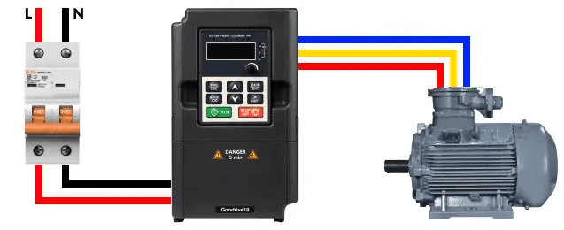
Can a 3 phase motor run on single phase – using inverter
1.1 Single phase 220V inverter to three phase 220V
The structure diagram of a 220V single-phase inverter includes three parts:
+ Rectifier: uses 4 diodes, which are similar to check valves used in plumbing systems. They allow current to flow in only one direction; the directions shown by the arrow in the diode symbol.
>>See also: Full wave bridge rectifier circuit diagram (4 diagrams)
+ Capacitor: The voltage after passing through the rectifier bridge will be DC voltage, the voltage amplitude ranges from 0 – 310 VDC. We can get rid of the AC ripple on the DC bus by adding a capacitor. A capacitor operates in a similar fashion to a reservoir or accumulator in a plumbing system. This capacitor absorbs the ac ripple and delivers a smooth dc voltage. The voltage on the DC bus becomes approximately 310VDC.
+ Inverter: Microprocessor controls six semiconductor switches (IGBT) to convert DC voltage into 220V three-phase AC voltage (RMS). Note that the inverter does not produce a sine voltage. This inverter waveform would not be a good choice for a general purpose distribution system, but for motor control it is perfect.
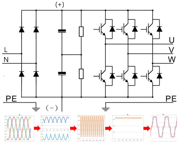
Structure of single phase inverter
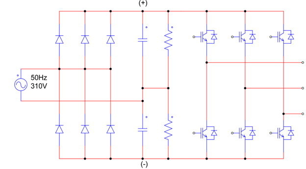
1.2 Inverter from single phase 220V to three phase 380V
The structural diagram of this inverter also consists of three parts; the only difference from the single-phase inverter is that in the rectifier part, one power phase goes into the diode bridge, the other power phase goes between the two capacitors. In the positive cycle, the capacitor above will be charged (310V), In the negative cycle, the capacitor below will be charged (310V). And we obtain a total voltage of approximately 620VDC.
The 620V DC voltage is then inverted, at the output we will obtain a three-phase voltage of 380V (rms) to control the three-phase motor.
Advantages of running a three-phase motor with single-phase electricity using an inverter:
+ In direct motor starting methods, when starting, the motor current will increase many times compared to the motor’s rated current. When using an inverter we can change the time the motor starts. Helps the motor start smoothly.
+ The inverter can control the rotation speed of the motor. Unlike other methods, when using an inverter, we only need to change the output frequency to control the speed of the three-phase motor (n = 60f/p).
+ Reduce Energy Consumption and Energy Costs. If you have an application that does not need to be run at full speed, then you can cut down energy costs by controlling the motor with a variable frequency drive.
+ The inverter has many protection functions for the motor such as overload protection, low load protection, and phase loss protection. Therefore, using an inverter helps limit regular maintenance.
>>> Related articles:
4 Star Delta Starter control circuits