Working principle of half wave rectifier circuit with capacitor filter, application of half wave rectifier in power supply circuits. How to choose the appropriate capacitor value?
1. Half wave rectifier circuit with capacitor
1.1 Why do we use capacitor in rectifier circuits?
We all know the waveform of half wave rectifier circuit is DC. voltage with ripples. This voltage cannot work with IC or Digital circuit. The large ripple also makes the output voltage of the half-wave rectifier circuit smaller than other rectifier circuits.
Therefore, it is necessary to reduce the ripple. To do this, people often use capacitors parallel with the load. The figure below is the output waveform of the half-wave rectifier circuit in the two cases: using capacitors and without using capacitors.
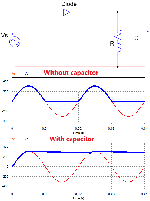
Half wave rectifier circuit with capacitor filter
1.2 Working principle of half wave rectifier with capacitor filter
The capacitor is connected in parallel with the output load, so the voltage across the capacitor equals the output voltage (Vo = Vc).
+ In the first half-cycle: the voltage increases from 0V to the peak voltage Vmax and the capacitor starts to charge (Vo = Vc = Vs)
+ When the supply voltage reaches the peak value, the supply voltage will decrease. The capacitor begins to discharge through the load, and the output voltage gradually declines. Because the voltage across the capacitor is larger than the output voltage (Vo = Vc > Vs), the diode is reverse biased, so the diode will not conduct. The voltage value depends on the discharge time of the capacitor.
+ When the voltage on the capacitor Vc is less than the supply voltage, the capacitor will charge again until the capacitor is fully charged (Vc = Vmax).
=> Due to the discharge of the capacitor, the output voltage of the half-wave rectifier circuit has a small ripple. If the capacitor value is large enough, then the output voltage waveform will be a straight line. The average output voltage will equal the peak voltage Uo = Umax.
1.3 Selecting capacitor value
The capacitor is chosen for the discharge time of the capacitor is much longer than the time between the two peak voltages. Call T is the period of the supply voltage, then:
R.C >> 2T
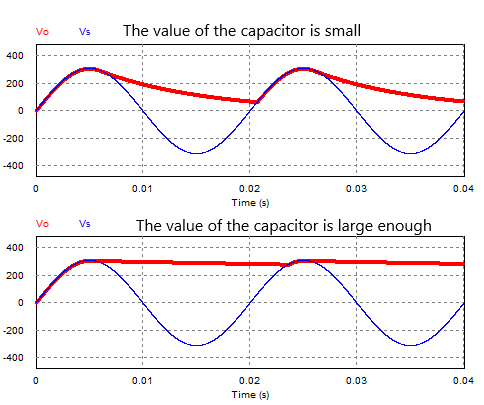
If the capacitor value is too large, it will be costly. If the capacitor is too small, the ripple will be large. Choosing the exact value of the capacitor is quite complicated, so people often use software to simulate.
Video simulating the operation of a rectifier circuit using a capacitor
2. 5V Power Supply Circuit
Half wave rectifier circuits with a capacitor filter can use to create small-capacity DC power supply circuits. The figure below is an example of a 5V power supply circuit using 7805.
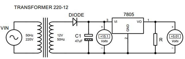
Power supply circuit using half wave rectifier circuit
A simple 5V power supply circuit will include a transformer, the diode, capacitor, resistor, and IC 7805.
+ 12V transformer: Change the supply voltage (220V, 50Hz) to 12 AC voltage (12V, 50Hz).
+ Diode: only allows current to pass through it in one
+ Capacitor: A capacitor is used to filter the output voltage.
+ IC 7805 converts the input DC voltage of 15V into a fixed voltage of 5V.
>>> See also:
Single phase half wave uncontrolled rectifier circuit (4 circuits)
Three phase half wave rectifier circuit (4 circuit diagrams)