Learn about the principle of three-star delta reverse forward circuit diagrams using a switch, push button, and PLC. Analyze the advantages and disadvantages of each type of circuit.
Dynamic Circuit Diagram
Star delta reverse forward circuit can be controlled by various methods such as push button, switch, microcontroller, and PLC. But they share the same dynamic circuit diagram. The figure below is the schematic diagram of star delta starter circuit and reversing the motor rotation.
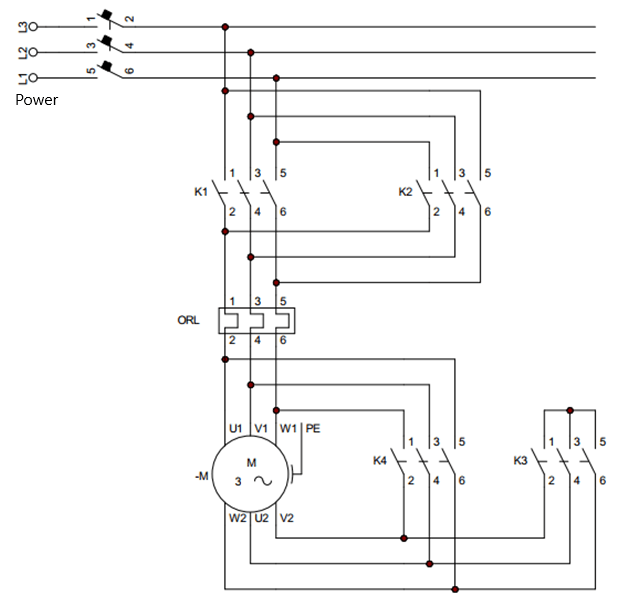
Dynamic circuit diagram
This circuit diagram combines a motor reversing circuit and a star-delta starting circuit of three phase motor.
+ MCB 3P is used for manual power switching and short circuit protection for dynamic circuits.
+ Contactor K1 connects three motor wires to power. Contactor K2 is used to reverse the order of 2 out of 3 phases (change the order of phase 1 with phase 3).
+ The thermal relay connected in series with two contactors K1 and K2 will protect the motor against overload both in forward or reverse rotation and in star or delta operation.
+ Use two contactors K3 and K4 to switch star and delta modes.
– When contactor K3 is closed, the circuit runs in star mode. The three contacts above connect to a point, and the lower three contacts connect to the three wires of the motor. The other three wires of the motor are connected to the end of the thermal relay.
When contactor K4 is closed, the circuit operates in delta mode. The top three contacts of the contactor connect to the three terminals of the motor, and the lower three contacts connect to the other three wires of the motor. Note: the beginning of this coil will have to connect to the end of the other coil (U2 connects to W2, V1 connects to U2, W1 connects to V2).
3 star delta reverse forward control circuit diagrams
1. Control circuit using three position switch
The circuit below uses a three-position switch to control star-delta starting and rotation for a three-phase motor.
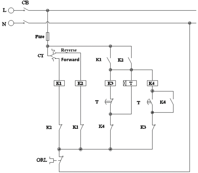
Control circuit diagram using three position switch
The three-position switch has three states: ON1 – OFF – ON2. When the switch is in the OFF position, the contacts open. When the switch is in the ON1 or ON position, the left or right contact of the switch will close.
Working principle
+ When the switch is turned to ON1 position (forward), coil K1 is energized; contactor K1 closes and normally open contact K1 closes. Normally open contact K1 closes, so coil K3 and Timer T are energized. The motor is now running in star mode, and Timer T starts counting.
When Timer T counts up to the preset time, the normally open contact of Timer T closes, and the normally closed contact of Timer T opens. So coil K3 is de-energized, and at the same time coil K4 is energized. Then the normally open contact K4 closes, and the normally open contact K4 opens. So Timer T is de-energized, and the motor is now running delta mode.
+ When the switch is turned to ON2 position (reverse), contactor K2 closes. The motor runs in the reverse direction, and the circuit begins to perform star-delta starting as in the forward-running case.
+ Coil K1 in series with normally closed contact K2, coil K2 in series with normally closed contact K1. Therefore two contactors K1, K2 cannot be closed at the same time. Because if contactor K1, K2 is closed at the same time, it will lead to a short circuit. Same for contactors K3 and K4, only one contactor is closed at a time.
Advantages and disadvantages:
+ The advantage of this circuit is simple, easy to operate, and low cost.
+ The disadvantage of the control circuit using a switch is: The motor will automatically run again if the switch has not been turned to the OFF position (in the event of power return).
2. Control circuit using push button
The downside of the switch is that its contacts do not return to their original position after a power failure. Therefore, people will replace the switch with ON and OFF push buttons. The control circuit diagram using push buttons is presented as shown below.
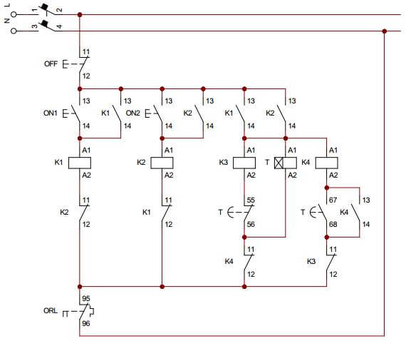
Circuit diagram of star delta reverse forward use push button
The OFF button is normally closed; when we press this button, its normally closed contact will become open. The ON push button is normally opened; when we press this button, its contact will become close. When we release our hand, its contact will return to its original state.
Working principle:
This circuit uses push button ON1, OFF controls contactor K1. When ON1 button is pressed, contactor K1 closes; this permits the current to pass through these contacts to the load, the motor rotates in the forward direction. At the same time, the normally open contact K1 closes and keeps the closed state of contactor K1.
When the ON2 button is pressed, contactor K2 closes, and the motor runs in reverse. Normally open contact K2 closes to maintain the closed state of contactor K2.
When normally open contact K1 or K2 is closed, the motor will switch star-delta like in a circuit using a switch.
Advantages and disadvantages
This circuit is more complicated than the one above because it uses self-holding contacts. But this circuit solves the disadvantage of the switch circuit, so the star delta reverse forward circuit using the push button is widely used.
3. Star delta reverse forward circuit using PLC
PLCs are programmable devices used for automated applications. Circuit using PLC will simplify the circuit and easily change the function of the circuit.
In the star delta circuit using PLC, we will not need to use the Timer when switching automatically. The wiring diagram with the PLC is drawn as follows.
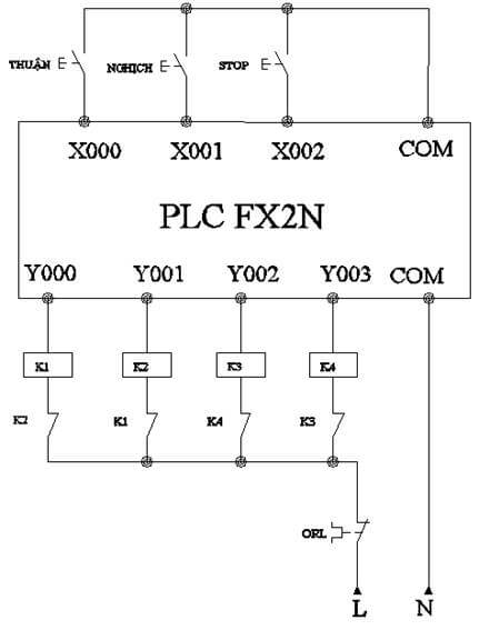
Sơ đồ mạch điều khiển dùng PLC
+ PLC input X0, X1, X2 connects to the forward, reverse and stop push buttons.
+ PLC outputs are relay contacts connected to contactor coils and 220V power.
PLC programming:
+ When the forward button is pressed, X0 is turned on; because the circuit is closed, y0 is activated. In the program the normally open contact y0 in parallel with X0 has the function of keeping its own state. So we don’t need the self-holding contact in parallel with the push button in this circuit.
When the PLC output pin y0 is enabled, the y0 pin will be connected to the COM pin. Therefore, the contactor coil K1 is energized, and the motor runs in the forward direction.
+ Similarly, when the reverse play button is pressed, y1 is turned on. At this time, contactor K2 closes, the motor rotates in the reverse direction.
+ When output y0 or y1 is turned on, y2 is enabled. The motor runs in star mode, and the timer in the PLC starts counting. Since star delta starts only once when the motor operate, the program uses the rising edge pulses of y0 or y1.
+ When the timer counts to the preset time, output y3 is enabled, and y2 is turned off. The motor is now running in delta mode.
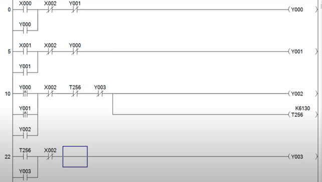
Program on PLC
Advantages and disadvantages:
The advantage of the control circuit using PLC is the ability to expand more functions. The wiring circuit using PLC will be simplified. The reliability of the PLC is high.
The disadvantage is that the cost of PLC is quite high, suitable for relatively large-scale applications. Requires users have basic knowledge of PLC programming.
>>> See also:
4 star delta starter control circuit diagram