Learning about the operating principles of 4 star delta starter control circuit diagram schematics, advantages and disadvantages of each circuit. How to calculate and select components of star triangle circuit.
What is star delta stater?
What is star delta starter control circuit diagram schematic?
The star delta starter control circuit diagram is a circuit used to reduce the starting current of three phase squirrel-cage asynchronous motor. When starting the motor will run in star connection mode. When the motor speed increases to 75% of the rated speed, the motor switches to delta connection mode with the rated speed.
If the motor runs in star mode, the voltage applied to each phase is reduced by √3 times, and the starting torque is reduced by 3 times. We can see a significant reduction in the starting current, especially when using a large motor load.
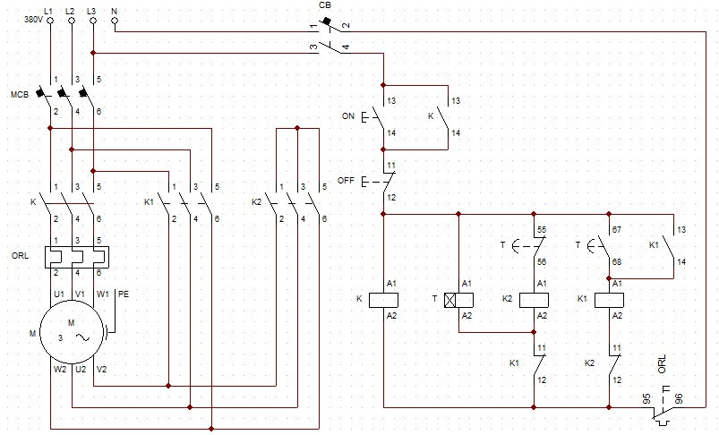
The figure below is the actual star delta starter circuit that controls the automatic switching by Timer, with phase loss protection.
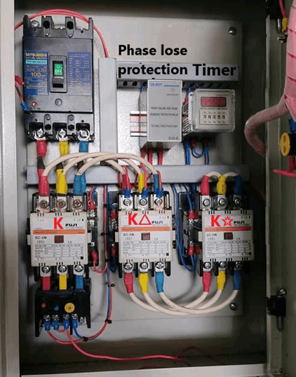
Star delta starter cabinet
Why star delta starter is used
The 3-phase asynchronous motor is the most commonly used actuator in industry. With the advantages of high applicability, ease of control, high reliability, a wide range of capacities.
A major disadvantage of 3-phase induction motor is that when the motor starts, the current is 5-7 times higher than the current in normal operation. This can cause interference or voltage drop across the mains voltage, affecting other equipment.
Therefore, it is necessary to reduce the starting current, especially with large capacity motors. Some methods of reducing the starting current of the motor can be listed as:
+ Add resistance to the rotor windings
+ In series with reactor
+ Use a self-transformer
+ Star delta starter
+ Use soft starter, inverter
Among these methods, the star delta starter control circuit diagram is the most commonly used. Since this circuit is simple, it is less expensive but effective. The starting current will be 3 times less than the rated current
Star delta motor connection
Three phase motor using the star delta starter method will have 6 wires. When connecting to star mode, 3 terminals will be connected to the source and 3 other terminals will connect together. When connecting in delta mode, a terminal of one coil will be connected to a terminal of the other coil. Specifically:
+ Star connection: 3 terminals U1, V1, W1 connected to the source, 3 terminals U2, V2, W2 connected together at one point.
+ Connect delta: U1 connect to W2, V1 connect to U2, W1 connect to V2.
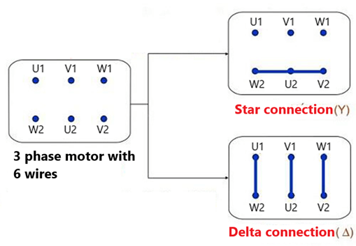
Diagram of star delta motor connection
Features of the star-delta connection circuit
+ Motor requirements
For the star-delta connection circuit, a motor with medium power is used. If the motor is too large, soft starter or inverter should be used. If the motor is too small, the current will not affect the supply voltage, so there is no need to apply star delta starting.
The motor can be connected in star and delta mode when the motor’s label has the symbol △/☆: 380/660V. Because the voltage in some countries is 3 phase 380V. For motor type with symbol △/☆: 220/380V, only delta mode can be connected with 220V three-phase voltage. Therefore cannot connect to star delta starter.
+ Transient current during star-to-delta switching
When the motor runs to 75% speed, it will switch from star to delta mode. The motor will start with low voltage and then switch to run at rated speed, rated torque.
Then there will be a transient current, which is sometimes even larger than when starting directly.
Star delta starter control circuit diagram schematic (4 circuits)
1. Star delta starter control circuit diagram schematic using push button
The figure below is a manually controlled star delta starter control circuit diagram. Using two sets of ON and OFF push buttons for each star mode and delta mode.
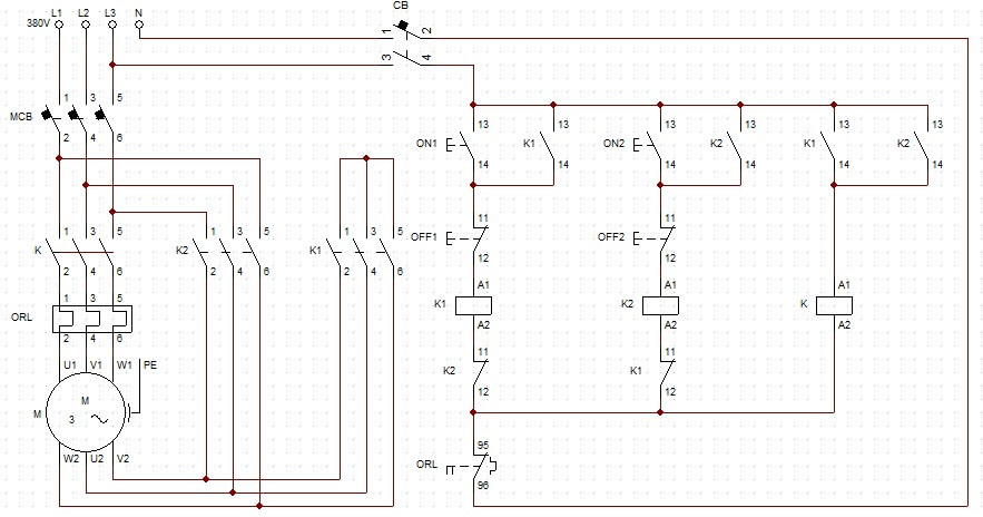
Circuit controlled by push button
+ When we press ON1 button, contactor K and K1 are energized. Normally open contact K1 (13 14) will close to keep the state of the circuit when push button ON1 returns to the initial state. The main contacts K and K1 are closed, so at that time the 3 wires U1, V1, W1 connected to the source and 3 wires U2, V2, W2 connected together. So now the motor is working in star mode.
+ We will wait for the motor to accelerate for a while, then we press OFF1, the coil K and K1 are not energized. At this point, the motor is disconnected from the power supply.
+ When we press the ON2 button, similarly the main contacts K2 and K close. At this point, we can see that the motor has a terminal of this coil connected to a terminal of another coil: U1 connects to W2, V1 connects to U2, W1 connects to V2. Therefore the motor will work in delta mode.
+ Then, the induction motor will work permanently in delta mode. The motor is now running at rated speed and rated power.
+ Press OFF2 to stop the motor.
*** The advantage of the manual control circuit is that the operating principle of the circuit is simple, easy to understand but easy to cause errors. Because the adjustment of the switching time is not the same, it depends on the operator.
2. Automatic circuit using Timer
The star delta starter control circuit diagram uses a pair of ON, OFF push buttons to control running and stopping. Use a timer to switch automatically from star to triangle mode. We will adjust the switching time depending on the acceleration time of the motor and depending on the load.
+ When the ON button is pressed, contactors K and K2 close immediately, the motor now runs in star mode. Normally closed of K closes keeping the state of the circuit instead of the ON button. At the same time, the timer coil is energized, so the timer starts to count.
+ When this timer counts to the previously set time, the normally closed contact T (55 56) opens and disconnects contactor K2 from the power source. At the same time, the normally open contact T (67 68) closes to supply power to coil K1. The motor will run in delta mode.
+ When the OFF button is pressed, no matter what mode the motor runs, it will decelerate until it stops spinning.
When the motor is overloaded, the thermal relay is activated. Opening the normally closed contact ORL (95 96) in the control circuit. As a result, the contactor coils lose power and the motor stops rotating.
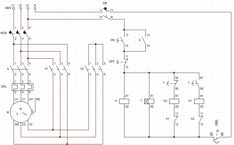
Star delta circuit using timer
Refer to the video about the principle of star delta circuit – The Engineering Mindset
3. Star delta starter control circuit diagram with timer (optimal)
We can see in the above circuit after the motor has finished starting. And when the motor works in delta mode, the Timer is still powered. This causes the circuit to consume power and affects the life of the timer.
Therefore the circuit below uses normally open contact K (13 14) in parallel with normally open contact of T (67 68). When contact K1 13 14) is closed, the circuit does not need to use timer T.
Timer T coil will be connected in series with normally closed contact K1 (11 12). So after the circuit has switched to delta mode, the Timer coil is disconnected.
Star delta starter control circuit diagram use timer – optimization circuit
4. Circuit using PLC
– Wiring diagram
+ PLC input reads the status of two push buttons ON and OFF at pins I1 and I2.
+ PLC output controls 3 contactors K, K1 and K2 with outputs with pins Q1, Q2, Q3. The normally closed contact of the thermal relay ORL will be in series with the coil of contactor K.
The figure below is a wiring diagram of the star delta starter control circuit diagram with a PLC.
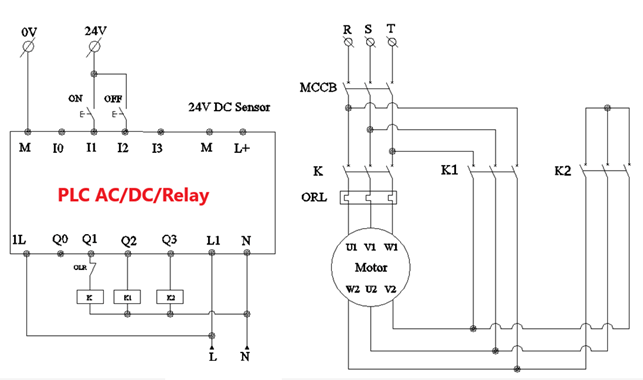
Wiring diagram of star delta starter using PLC
Program on PLC
The operation of the program on the PLC is as follows:
+ PLC will read the status of two buttons: ON, OFF. When the ON button is pressed, Q1 turns on, coil K is energized and Timer T1 starts counting time.
+ At the same time when Q1 turns on, it makes Q2 turn on. Therefore contactor K2 is energized, at this time contact K and K2 are both closed, so the motor runs in star mode.
+ When T1 counts to the preset time of 5s, normally closed contact T1 opens, so Q2 turns off and contact K2 opens. At the same time, the normally open contact of T1 closes, Q3 turns ON, so contact K1 closes, the motor runs in delta mode.
+ When the OFF button is pressed, Q1 turns off, the circuit stops working
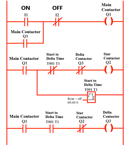 PLC program
Calculation and selection of equipment
Assume that we need to design a star-delta circuit for a three-phase motor with symbol D/Y: 380/660V, rated power: 35kW, power factor: 0.8. We will calculate to select the device for the star delta circuit:
We have P = √3UICos φ => I = P/ (√3UCos φ) = 35×1000/(√3x380x0.8) = 66A.
=> Therefore, the rated current of the motor is IM = 66A.
– Circuit breaker:
Selecting CB with a current twice as large as the rated current of the motor
=> Selecting CB: 140A
– Selecting contactor:
When choosing a contactor, we need to multiply the motor rated current by a safety factor k. k from 1.3 to 2 depending on whether the contactor operates continuously or intermittently. Assuming k = 1.5, we have:
Ic = IM x 1.5 = 99A.
+ In delta mode, 2 contactors K and K∆ conduct, so the current for each contactor:
ID = Ic/√3 = 57A
=> Selecting contactor K and K: 60A
+ In star mode, the current is reduced by 3 times, so the current through K☆:
IY = Ic/3 = 33A
=> Select contactor K☆ is 35A
– Selecting thermal relay
The motor will work permanently in delta mode, so the thermal relay should be selected according to the load current of the contactor K. That is equal to the motor rated current divided by √3. We have:
IORL = IM/√3 = 66/√3 = 38A
=> Selecting thermal relay 28 – 40A
>>> Related posts:
What is contactor? The most detailed article about contactor