In the previous article, we learned the principle of 4 bridge rectifier circuits using diodes. Today’s article will continue to learn about single phase fully controlled bridge converter (5 diagrams).
1. Single phase fully controlled bridge converter (3 circuits)
1.1 Rectifier circuit with R load
The controlled rectifier circuit uses four thyristors instead of diodes.
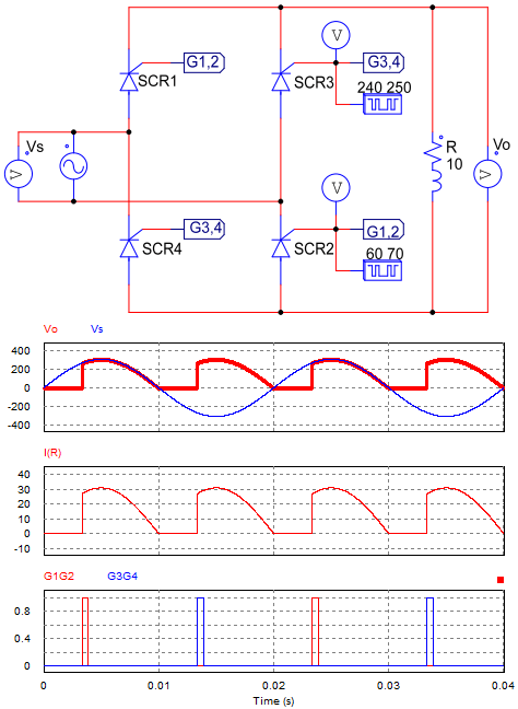
Single phase fully controlled bridge converter with R load
Working principle
+ During positive half cycle: SCR1 and SCR2 are forward biased. When the trigger pulses G1 and G2 appear, SCR1 and SCR2 will conduct. Current will pass through SCR1, R, and SCR2; If we ignore the voltage drop on the SCR, the output voltage is equal to the source voltage: Vo = Vs.
+ During the negative half cycle: SCR1 and SCR2 are reverse biased while SCR3 and SCR4 are forward biased. When an trigger pulse G3, G4 is applied to the control pins of these thyristors, SCR3 and SCR4 will conduct. Current will pass through SCR3, R, and SCR4; The current flowing through R load in this case is in the same direction as the current flowing through R load for the positive half cycle (and Vo = |Vs|).
1.2 Single phase fully controlled bridge converter with RL load
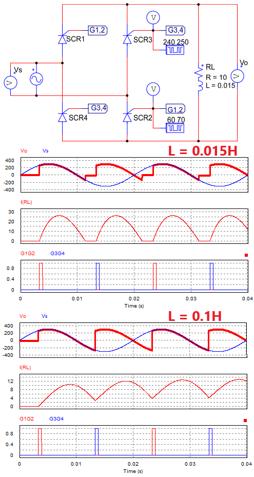
Controlled bridge rectifier circuit with RL load
Operation Principle:
In the positive half cycle (Vs > 0): When the trigger pulses G1 and G2 appear, SCR1 and SCR2 conduct.
In the negative half cycle (Vs < 0): SCR1 and SCR2 are reverse biased while SCR3 and SCR4 are forward biased. When the RL load suddenly loses power, the inductor generates a current in the same direction as the previous current. Therefore, even though no trigger pulse has appeared, SCR3 and SCR4 will still conduct. The time that the load generates current depends on the value of L:
+ L = 0.015H: the load generates a current in a short time. When the RL load runs out of energy, the output voltage is zero, and the output current is zero.
+ L = 0.1H: the load generates current until there is a control pulse G3G4, so the output current is continuous.
1.3 Rectifier circuit with RLE load
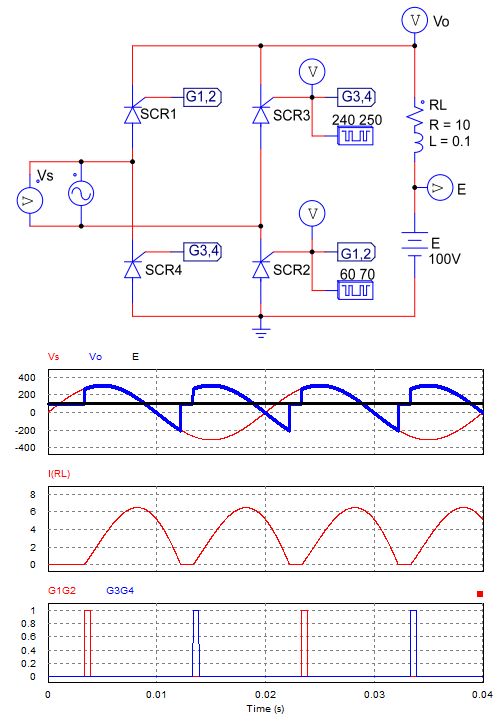
Rectifier circuit with RLE load
The difference between the RLE load rectifier and the RL load rectifier is:
+ When the supply voltage is less than E, the SCR is reverse biased.
+ When the SCR is not conducting, the output voltage equals E (Vo = E). And of course, when the SCR conducts, the output voltage is equal to the source voltage (Vo = Vs).
=> We see that with RL and RLE load: Single phase fully controlled bridge converter circuit has negative voltage parts.
2. Half controlled bridge rectifier circuit (2 circuits)
Semi-controlled bridge circuit will use two Diode and two SCR. The advantage of a half-controlled bridge rectifier circuit is:
+ It can maximize the control angle.
+ No negative voltage part like in a fully controlled bridge circuit.
For the Half controlled rectifier circuit with resistive load, the output waveform is the same as the fully controlled bridge circuit. Therefore we will only learn about half-controlled rectifier circuits with RL load.
2.1 Asymmetric half-controlled rectifier circuit
The asymmetric half-control bridge circuit has the following connection: two SCRs are connected in one column, two diodes are connected in another column of the bridge circuit.
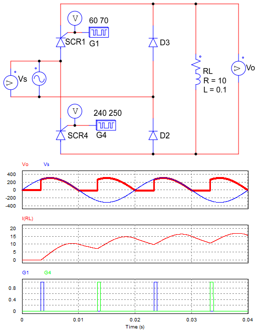
Asymmetric half-controlled rectifier circuit with load RL
Working principle:
+ In the positive half cycle: When there is a trigger pulse (G1), SCR1 and D2 conduct.
+ In the negative half cycle: When the RL load loses power suddenly, the inductor will generate current through D2, D3 and RL load. So the output voltage is zero while the output current is greater than zero (Vo = 0, Io > 0).
When there is a control pulse (G2), SCR4 and D3 will conduct. The output voltage is greater than 0 Vo = |Vs|.
=> The output voltage has no negative voltage parts, the current through the load is continuous.
2.2 Symmetrical half-controlled rectifier circuit
The symmetrical half-controlled bridge circuit diagram: SCR1 in series with Diode D4 on one column of the bridge circuit. SCR3 and Diode D2 are connected in series in another column.
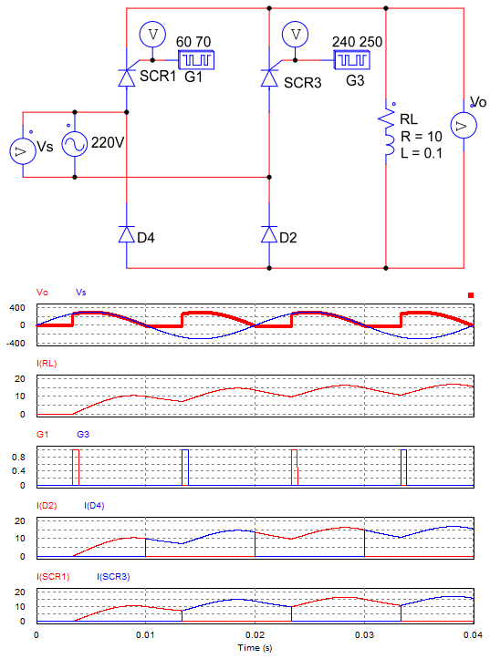
Symmetrical half-controlled bridge rectifier circuit
Operation Principle:
+ In the positive half cycle: SCR1 and D1 are forward biased. When there is a trigger pulse (G1) placed on the control pin of SCR1, then SCR1 and Diode D2 will conduct, so Vo = Vs.
+ In the negative half cycle: When RL load is disconnected, the inductor generates current through SCR1 and D4, so Vo = 0, Io > 0.
When the G3 trigger pulse appears, SCR3 and D4 lead: Vo = -Vs >0.
=> We observe that the output waveform of this circuit is similar to the waveform of the asymmetric circuit. The output voltage has no negative value, and the load current is continuous.
>>> Related Articles:
Full wave bridge rectifier circuit diagram (4 diagrams)
Single phase half wave uncontrolled rectifier (5 circuits)