In this article, we will learn about 2 and 3 wire start stop diagram. This article’s content will include a circuit diagram, operating principle, and simulation video.
2 wire start stop diagram control motor
a. Circuit diagram
This diagram is the most basic circuit that uses a switch to control a motor through a contactor. When the state switch is open, the motor will not work. When the state switch is closed, the motor will start to rotate.
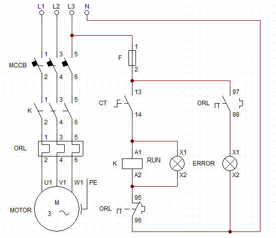
2 wire control circuit
+ The dynamic circuit that controls the start and stop of a three-phase motor includes CB, contactor, and thermal relay. The circuit breaker will be in series with the main contact of contactor K and thermal relay ORL to go to the motor.
+ The control circuit uses a two-position switch in series with the coil of the K contactor, and the normally closed contact of the ORL thermal relay.
b. Working principle
+ When the switch is in the open position, the coil of contactor K is not energized. The dynamic contact of contactor K is in the open state, so no voltage is applied to the motor. The motor is not running at this time.
+ When we move the switch to the closed position, the contactor coil K will be energized. At this time, the dynamic contact of contactor K changes from the open state to the closed state. The motor starts running, and the Run lamp will light to indicate that the motor is running.
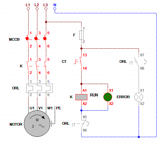
When the switch is in the open position, the motor will run
3 wire start stop diagram
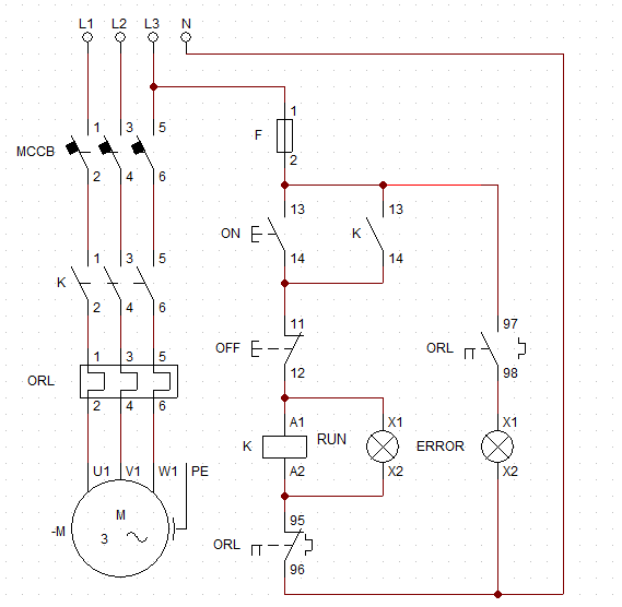
3 wire control circuit diagram
The dynamic circuit of 2 wire start stop diagram is the same as 3 wire start stop diagram. However, the control circuit of this circuit uses two push buttons instead of using a switch.
Unlike a two-position switch, when we stop applying force to the push button, its contact will return to its original position. Therefore, to keep the motor running, the normally open contact of contactor K is used in parallel with the ON button push button. When we press the ON button, the normally open contact of contactor K will close. So the motor will operate until we push the OFF button, and the circuit will return to the initial state.
In industrial circuits, three-wire control circuits use more than 2 wire control circuit because of the safety of the 3 wire control circuit. After an incident such as power failure or overload, that circuit will return to the initial state, so the motor does not automatically restart.
Simulation Video
>>> Related Post:
Start stop contactor wiring diagram (3 circuits)