In this post, I will present reverse forward control circuit diagram. Learn about the circuit diagram, operating principle, simulation video, and advantages of forward reverse circuit diagram.
Basic forward reverse control diagram
a. Circuit diagram
The figure below is a basic control circuit diagram for reversing a three-phase motor using a three-position switch.
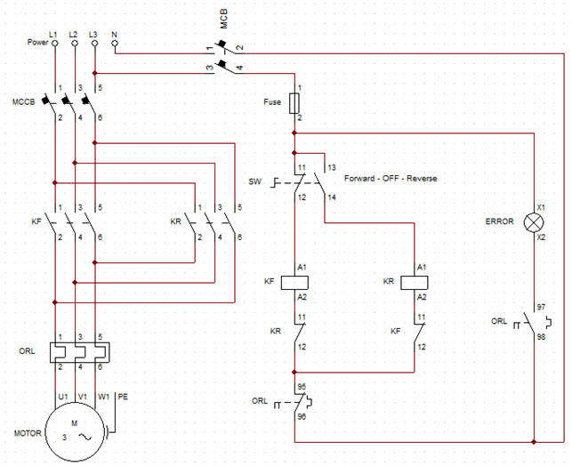
Basic reverse forward control circuit diagram
b. Working principle:
+ When the main contact of KF contactor is closed, the motor runs in the forward direction. Conversely, when the main contact of KR contactor is closed, the motor is energized to rotate in the opposite direction. Because when we change the order of the phase supplied to three phase motor, it will change the direction of the rotating magnetic field, leading to a change in the direction of the motor rotation.
>>> Details of the principle of reversing the three-phase motor have been detailed in the previous article: How to reverse a 3 phase motor with Switch, PLC, Inverter (5 circuits)
+ When the switch is turned to the forward position, the coil of the KF contactor will be energized. The dynamic contact of the KF contactor closes, and the motor rotates in the forward direction. The normally open contact of KF will open to ensure that the KR contactor will not close while the motor is rotating forward.
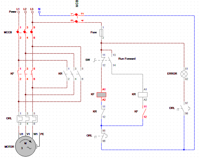
Motor rotates in the forward direction
+ When the switch is turned to the reverse position, the motor will be supplied with power through the dynamic contact of the KR contactor. The motor will rotate in the opposite direction. The normally closed contact of the KR will also open to prevent the KF contactor from closing when the motor is in reverse.
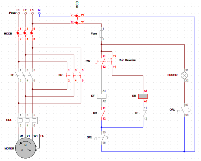
The motor rotates in the reverse direction
+ When the motor is overloaded for a period of time, the thermal relay will be affected and change its state. The normally closed contact of the ORL opens to stop power to the motor, protecting the motor from damage. At the same time, the normally open contact of the ORL closes, causing the fault light to light up, indicating that the circuit is having trouble. The circuit can only work again after we reset the thermal relay.
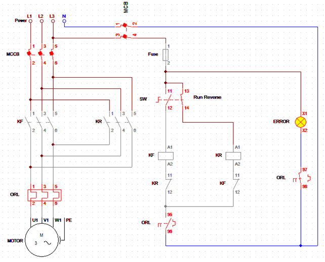
The circuit is in overload error state
c. Conclusion
The circuit principle is simple, easy to use, suitable for reversing control of small-capacity motors. The disadvantage of the circuit is that when the motor is rotating, if we turn the switch to reverse direction, the motor will reverse the rotation immediately. In this state will generate a large current.
Changing the direction of rotation of a running motor requires a lot more energy than starting a motor. This large current may lead to the failure of the CB or affect other equipment. However, you can wait for the motor speed to zero and then reverse the direction motor to avoid the above problem.
Reverse forward control circuit diagram with timer
To overcome the disadvantages of the circuit above. It is common to use two OFF Delay timers to delay the reversing time, to ensure that the motor speed has decelerated to zero before the motor runs in the opposite direction.
a. Timer Off Delay
When voltage is applied to the timer coil, the timer’s normally closed contact opens immediately. When we cut the input power to the timer, the timer keeps the contact open until the timer counts to the preset time.
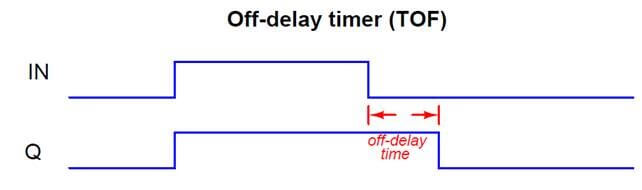
Off Delay Timer Working Principle (source: instrumentationtools)
In above picture, when the input signal is low, the contact remains in the previous state; this timer is called an off-delay timer. Off delay timer use in the motor cooling system. The cooling system design with a cooling motor, and it will run with the main motor. Thanks to the off delay timer, the cooling motor still runs for some time after the main motor has stopped.
b. Reverse forward control circuit with timer
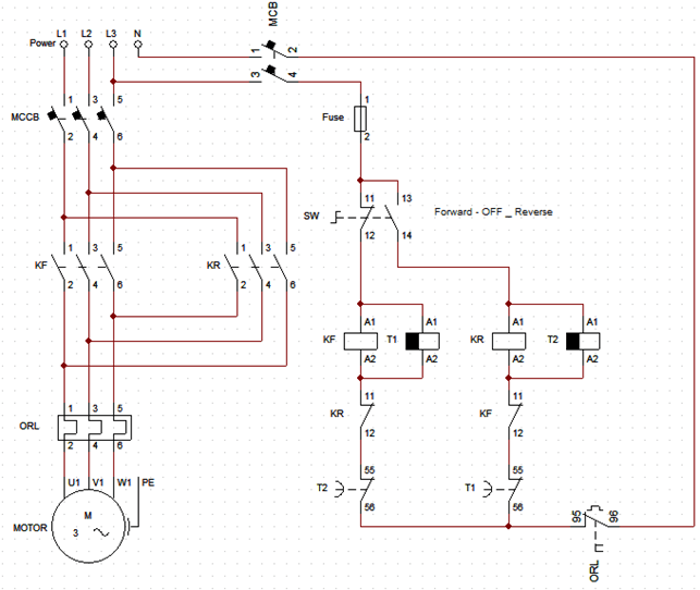
Reverse forward control circuit diagram with timer
This circuit utilizes two off-delay coils to prevent the forward and reverse coils from being energized until five seconds after turning on the reverse switch. There are two off-delay timers, each in parallel with each contactor coil. The forward contactor coil will connect to the normally closed contact of the 2 timer. And vice versa, the reverse contactor coil will connect to the normally closed contact of the 1 timer.
+ Assuming the motor is running in the forward direction, now Timer T1 is energized, so the normally closed contact of Timer T1 will open. If we push the switch to the reverse position, the motor will stop, and timer T1 will start counting time. When Timer T1 counts to the preset time, the contact of T1 will close, and at this time, the KR contactor is energized. The motor rotates in the opposite direction.
While timer T1 is counting time, there is nothing to prevent the motor from being rotated in the forward direction again, as the timer contacts of T2 remain closed.
+ Similarly, when the motor is rotating in the reverse direction, if we push the switch to the forward position, the motor will stop for a while. When timer T2 counts up to the preset time, the motor will rotate in the forward direction.