In previous posts, we learned about five half-wave uncontrolled rectifier circuits using diode. In this article will explain the working principle of a single phase half wave controlled rectifier with r load.
1. What is half wave controlled rectifier?
Uncontrolled rectifier circuit uses diode with fixed output voltage.
A single-phase controlled half-wave rectifier is a rectifier that uses a thyristor instead of a diode. The thyristor is the controlled switch, that is why this circuit is known as the controller rectifier. The output voltage of this circuit is controlled by varying the closing time of the SCR.
What is half wave controlled rectifier circuit?
Working principle of Thyristor: When the thyristors Anode terminal is negative to the Cathode. The thyristor is forward biased. When an trigger pulse is applied to the control pin of G, the thyristor will conduct. Because the thyristor can self-maintain conduction, the control pulse has a small width.
Since an AC sinusoidal voltage continually reverses in polarity from positive to negative on every half-cycle, this allows the thyristor to turn Off at the 1800 zero point of the positive waveform.
=> So by applying a Gate signal at the appropriate time during the positive half of an AC waveform, the thyristor can be triggered into conduction until the end of the positive half cycle. The smaller the SCR trigger angle, the larger the average output voltage.
2. Single phase half wave controlled rectifier with r load
2.1 Half wave controlled rectifier circuit diagram
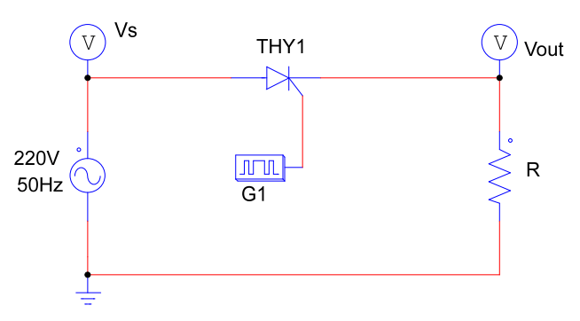
The figure below is the circuit diagram and waveform of a single-phase half-wave controlled rectifier circuit. The rectifier circuit is designed and simulated on Psim software.
+ Thyristor connected in series with the load is a resistor with value R = 10 Ohm.
+ Pin G of the thyristor is controlled by the Gating Block. The frequency of the control signal is equal to the frequency of the supply voltage (f = 50Hz). In the examples below, I use the trigger angle as 30 degrees, and the pulse width is 10%.
Single phase half-wave controlled rectifier with R load
2.2 Working principle
+ In the positive half (Vs >0):
* wt = 0 – 300: Thyristor does not conduct so the output voltage Vo = 0V.
* wt = 30 – 1800: Thyristor is forward biased. When a signal pulse is applied to the gate terminal G, the thyristor will conducts. The voltage on the load is now equal to the source voltage Vo = Vs.
+ In the negative half-cycle: Because thyristor is reverse biased, it will not allow current to pass. The output voltage in negative half-cycle: Vo = 0
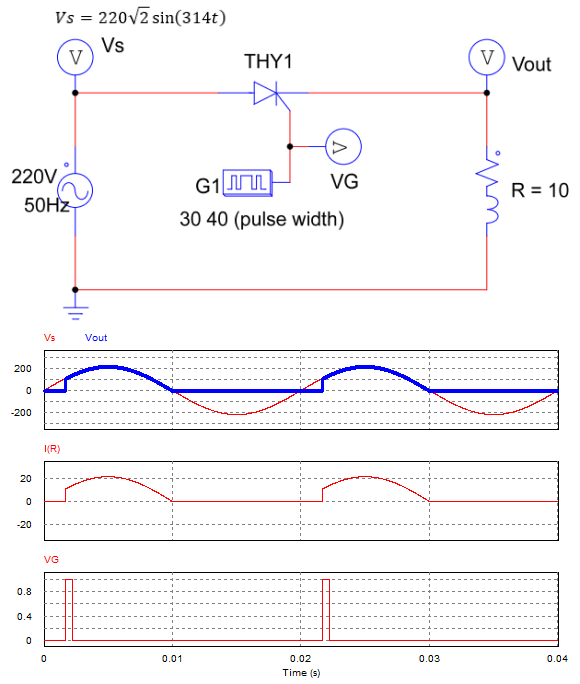
2.3 Single phase half wave controlled rectifier circuit simulation with R load
Half wave controlled rectifier circuit simulate on Psim software.
>>> Related posts:
Single phase half wave uncontrolled rectifier (5 circuits)
Star Delta Starter control circuit diagram schematic (4 circuits)
3 phase half wave controlled rectifier (2 circuits) – Detailed explanation