Working principle of single phase half wave controlled rectifier circuit (two circuits) with RL load. Disadvantages of rectifier circuit with RL load and how to fix it.
2 single phase half wave controlled rectifier circuits with RL load
1. Rectifier circuit with RL load
+ Circuit diagram
The single-phase half-wave controlled rectifier uses a single thyristor with RL load (L = 0.1H, R = 10). The output voltage and current waveform as shown in the figure below:
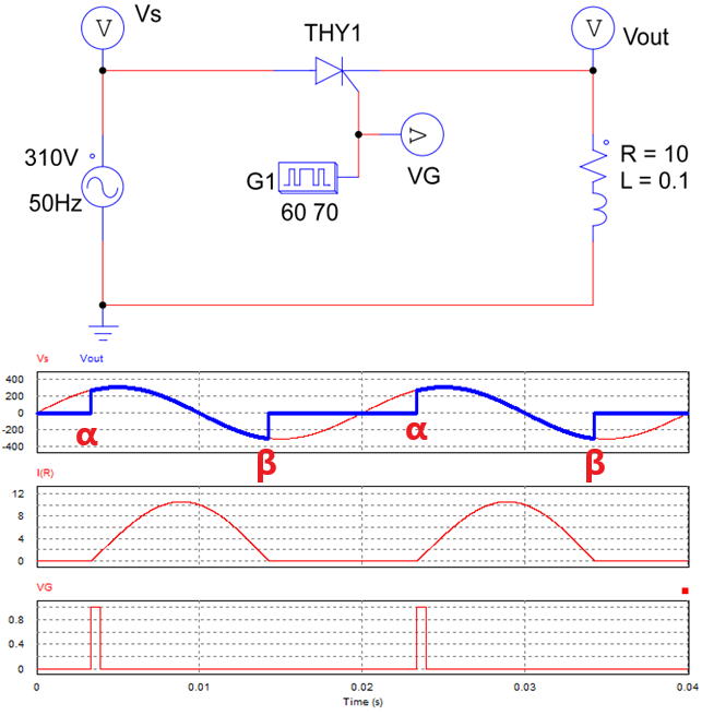
Single phase half wave controlled rectifier
+ Working principle:
In the positive half-cycle(Vs > 0): the thyristor is forward biased. When a control pulse is applied to the gate terminal at firing angle α, the thyristor starts to conduct. The output voltage will appear from ωt = α to ωt = π.
At ωt = π: thyristor goes turned OFF, but the current does not decay to zero because of the energy stored in the inductor. The negative voltage will appear from ωt = π to ωt = β (Vo = Vs < 0).
The load current decays to zero at ωt = β; the value of β depends upon the ratio R/L. From ωt = β to ωt = 2π, the output voltage is zero during this period. The angle β is called the extinction angle.
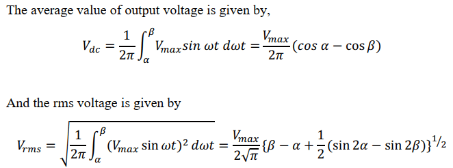
+ The formula for calculating the average value and the rms output voltage
The disadvantage of the rectifier circuit with RL load is that the output appears negative voltage. To eliminate negative voltage at the output voltage, we can use a capacitor or flyback diode as the following circuit.
1.2 Single phase controlled rectifier circuit with RL load and flyback diode
+ Circuit diagram
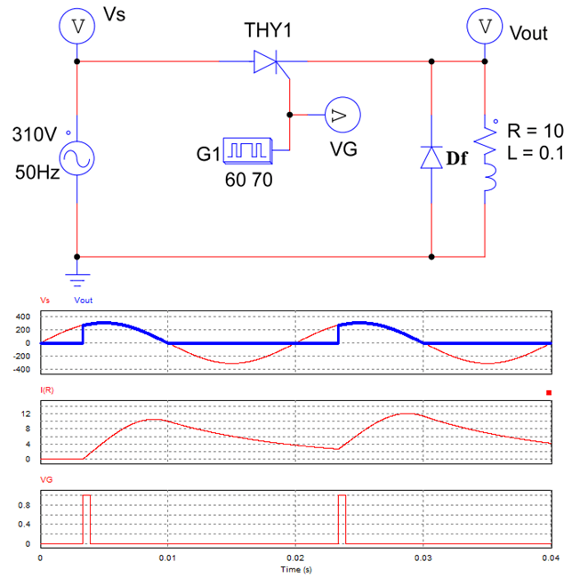
Single phase half wave controlled rectifier with RL load and flyback diode
+ Working principle
In the positive half cycle: the thyristor is forward biased. When a control pulse is applied to pin G of the thyristor, the thyristor will conduct. The output voltage equals supply voltage: Vo = Vs.
At ωt = π: thyristor goes turned OFF. The inductor emits energy creating the current through the diode Df and RL load. So the load current does not decay to zero. Because the diode Df conducts, the two terminals of the load RL are short-circuited (Vo = 0).
+ If the value of L is small: the load current decays to zero at ωt = β when the load runs out of energy.
+ If the L value is large enough (eg L = 0.1H): the load current is continuous (Io > 0).
Simulation video
>>> Simulate half wave controlled rectifier circuit on Psim software.
>>> Related posts:
Single phase half wave uncontrolled rectifier (5 circuits)
Three phase half wave rectifier circuit (4 circuit diagrams)