Working principle of two single-phase half-wave controlled rectifier circuits with RLE load. Simulate the operation of the rectifier circuit when changing the trigger angle of the thyristor.
Half wave controlled rectifier circuit with RLE Load (2 circuit)
1. Single phase half wave controlled rectifier with RLE Load
1.1 Ciruit diagram
Controlled rectifier circuit with RLE Load: R = 10, L = 0.1, E = 100, the circuit diagram is shown as follows:
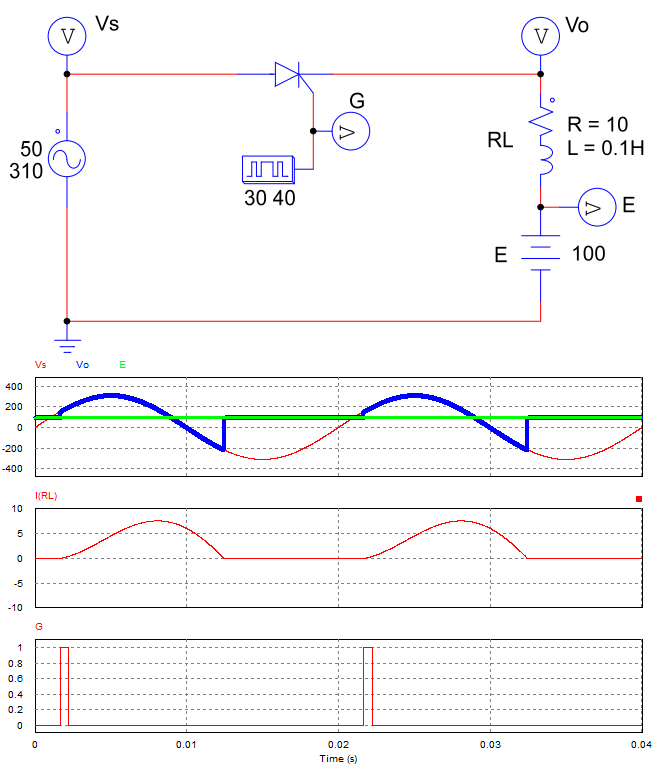
Half wave controlled rectifier with RLE Load
1.2 Working principle:
+ In the positive half-cycle:
* When Vs < E: The thyristor is reverse biased, so the thyristor does not conduct. The output voltage equals E: Vo = VRL + E = E = 100V, while the current through the load is zero.
* When Vs > E: The thyristor is forward biased. When the control pulse G appear, the thyristor will conduct like a closed switch. The output voltage is equal to the source voltage Vo = Vs.
* When the supply voltage Vs drops to less than E (Vs < E): even though the thyristor is reverse biased, it still conducts. Because the load emits energy, it outputs current in the same direction as the previous current. The output voltage Vo is still equal to the source voltage Vs.
+ In the negative half-cycle:
The thyristor continues to conduct until the load runs out of energy. When the thyristor stops conducting, the output voltage Vo = E.
2. Half wave uncontrolled rectifier with capacitor filter
2.1 Circuit digram
A single-phase half-wave controlled rectifier circuit uses a filter capacitor connected in parallel with the RLE load.
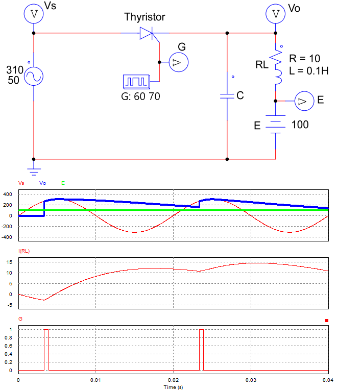
Half wave uncontrolled rectifier with capacitor filter
2.2 Working principle
+ When Vs < E: Thyristor is reverse biased so Vo = 0, Io = 0.
+ When Vs > E: Thyristor is forward biased. When an trigger pulse is applied to the control pin G, the thyristor will conduct (Vo = Vc = Vs). The capacitor starts to charge until the voltage across the capacitor equals the source voltage (Vc = Vmax).
+ When Vs < Vmax, the capacitor discharges, the output voltage Vo decreases slowly depending on the value of the capacitor C.
+ Until Vs > Vc, the control pulse G appears: the thyristor conducts, and the capacitor charges again.
>>> See also: Simulation video of Half wave controlled rectifier circuit with an RLE load when the trigger angle changes.
>>> Related Posts
Single phase half wave uncontrolled rectifier (5 circuits)
Three phase full wave controlled rectifier (3 Examples)
Three phase half wave rectifier circuit (4 circuit diagrams)