In this article, I would like to introduce the DC motor speed control circuit using Arduino. The principle of the most optimal motor speed control circuit and the explanation of the Arduino control program.
1. Principle of DC motor speed control using arduino
To change the speed of a DC motor, one can connect a resistor to the armature, change the voltage applied to the motor, and change the magnetic flux. Among these methods, varying the voltage applied to the motor stator is the most widely used method. Because these circuits have a wide speed regulation range and low cost. Typical is varying the voltage using PWM (pulse width modulation).
An electronic circuit is used to generate a signal whose the pulse width can be varied, the frequency of the signal pulse is fixed. This control signal is then amplified by semiconductor devices such as Transistor, Mosfet, and IGBT. Changing the pulse width will change the average output voltage and current.
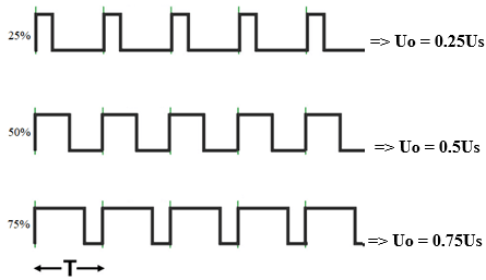
Method of controlling the speed of DC motor by PWM
2. Arduino program
For Arduino UNO can output a PWM pulse with a frequency f = 490Hz on pins 3, 8, 9, and 11; and a frequency f = 980Hz on pins 5.6.
The example below uses an Arduino to read the reference value from the potentiometer at pin A0 and output PWM at pin 9.
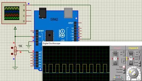
Simulating PWM output with Arduino
The Arduino program on the IDE software is written as follows:
// potentiometer connected to analog pin 9
int pwmPin = 9;
// variable to store the read value
int pot = 0;
// the setup routine runs once when you press reset:
void setup() {
}
// the loop routine runs over and over again forever:
void loop() {
// read the input voltage (0 – 1023) on analog pin A0
pot = analogRead(A0);
// analogWrite values from 0 to 255
analogWrite(9,pot/4);
}
AnalogRead reads potentiometer value at Analog pin 0. The value of this function is in the range from 0 – 1023, corresponding to the voltage from 0 – 5V.
The analogWrite function outputs a PWM pulse at pin 9, with a pulse width of 0 – 100% corresponding to the input value from 0 – 255.
Arduino simulation video output PWM pulse on Proteus software:
3. DC motor speed control using Arduino
3.1 Totem pole
A totem pole is an output driver circuit used to convert one level of voltage into another level of voltage.
For example, you want to drive the gate of MOSFET with the help of a microcontroller output pin. The output pin of the microcontroller generates a square wave of 5 volts. To fully control the gate of the N-channel MOSFET, you need to supply 12 volts to the gate terminal of the N-channel mosfet. To solve this problem you can use a totem pole. As shown in the figure below:
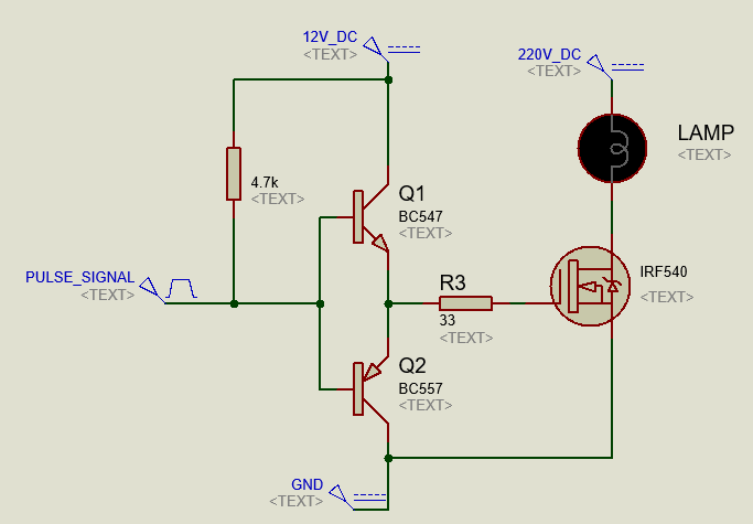
Totem pole circuit
Another advantage of the totem pole circuit is it can operate at high frequencies. Because when Mosfet turns off, the parasitic capacitor at the G terminal of Mosfet will discharge quickly through R3, Q2.
3.2 Working principle
The circuit diagram is drawn as shown below:
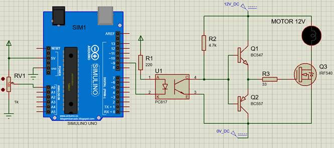
DC motor speed control circuit using arduino
Working principle: The Arduino will output a PWM pulse depending on the value of the potentiometer RV1 read. PWM pulses through the totem pole circuit will control Mosfet Q3. The Arduino is isolated from the power circuit by the Opto PC817.
+ When the signal pulse at pin 9 (PWM) is high: Because the Led inside the Opto PC817 does not light, the transistor inside the Opto will not conduct. Then resistor R2 will pull the voltage at the B terminal of the two transistors Q1 and Q2 to 12V. At this time, transistor Q1 is biased to conduct. Then there will be a 12V voltage applied to the gate terminal of the Q3 Mosfet, so Q3 conduct. The voltage measured at both ends of the motor is 12.
Because inside of the Mosfet there is a parasitic capacitance. To reduce the charging current for this capacitor, we add resistor R3 at the G terminal of the Mosfet.
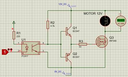
In case the PWM pulse voltage is high
+ When the PWM signal is low: Because the LED inside the Opto PC817 is lit, the transistor inside the Opto will conduct. The output of the Opto is now like the switch in the closed state. Then the voltage B terminal of the two transistors Q1 and Q2 pulls to 0V. Now Q2 conducts electricity; Mosfet parasitic capacitance Q3 discharges through resistors R3 and Q2. The control pin G of Mosfet Q3 is low, so Q3 does not conduct. So the measured voltage at both ends of the motor is 0V.
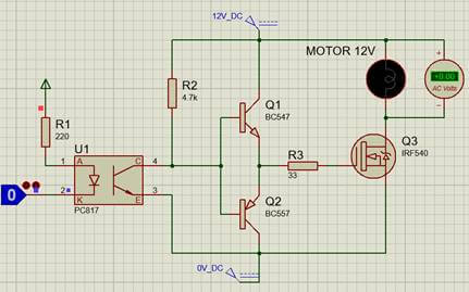
In case the PWM pulse is low
Video simulation of DC motor speed control circuit using Arduino:
Note: The PWM pulse and the output pulse are applied to the motor in opposite phase. And in the simulation software: the output pulse voltage is measured at the bottom of the DC motor, so when the pulse width value is 100%, the DC motor will stop rotating. Therefore, when the potentiometer value is Max, the motor speed is Max.
>>> Related Posts
Arduino controls the Servo motor speed (2 circuits).
Arduino controls servo with photoresistor – Wiring, code, video
Star Delta Starter control circuit diagram schematic (4 circuits)