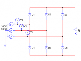
Three phase full wave rectifier circuit (4 circuits)
In this article, we will learn about three phase full wave uncontrolled rectifier circuit (4 circuits): Define, structure and principle of each 3-phase rectifier circuit. […]
In this article, we will learn about three phase full wave uncontrolled rectifier circuit (4 circuits): Define, structure and principle of each 3-phase rectifier circuit. […]
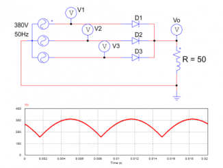
Three phase half wave uncontrolled rectifier circuit is a circuit used to convert 3 phase AC voltage into DC voltage using three diodes. This rectifier […]
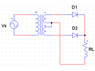
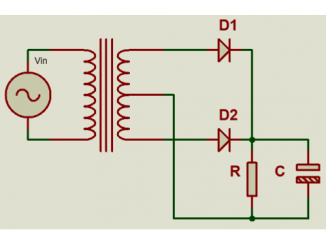
What is center tapped full wave rectifier? 7 schematic diagram of full wave rectifier circuit using 2 diodes, principle analysis and characteristics of each circuit. […]
In the previous article, we learned about the half-wave rectifier circuit. The disadvantage of half-wave rectifier circuit is low efficiency, large ripple because only allows […]
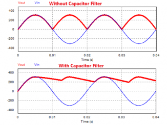
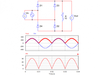
Two schematic diagram of full wave rectifier circuit with capacitor filter, why use capacitor filter in rectifier circuit. Full wave rectifier circuit with capacitor filter […]
Output waveform and operating principle of single phase full wave controlled rectifier circuit with R, RL and RLE load Circuit diagram and principle 1. Circuit […]
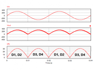
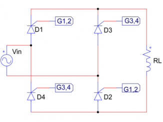
The bridge rectifier output voltage is a time-varying DC voltage. This article will learn about the output waveform characteristics and the formula for calculating the […]
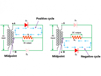
Learn about the output waveform characteristics of a full-wave circuit using two diodes. What are the disadvantages of center tapped full wave rectifier ? Output […]
Learn about full wave center tapped rectifier with capacitor filter. Principle of full wave rectifier circuit using two diodes and explain why filter capacitors are […]
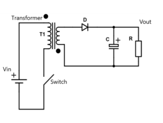
What is a flyback converter circuit? Explore the general diagram and principle of a basic flyback circuit. What is flyback converter circuit? The flyback converter, […]
Copyright © 2024 | Contact: Can Tho Automation